
User Manual
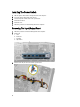
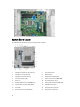

System Board Layout
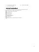
The following image displays the system board layout of the computer.
1. PCI Express x16 (wired as x4) connector 2. PCI Card connector
3. PCI Express x1 Card connector 4. Battery socket
5. PCI Express x16 card connector 6. Intruder Connector (Intruder)
7. Fan Connector (Fan_SYS) 8. Power connector (12V_PWRCONN)
9. Processor 10. Fan Connector (Fan_CPU)
11. Memory Module Connectors (DIMM_1-4) 12. Power Switch Connector (PWR_SW)
13. System power Connector (Mini_PWR) 14. SATA Drive Connectors
15. Front USB 16. Internal Speaker Connector
17. Front-Panel Connector (FrontPanel) 18. Thermal Sensor Connector
38