
User Manual


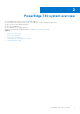

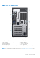

Table Of Contents
- Dell EMC PowerEdge T40 Installation and Service Manual
- Contents
- About this document
- PowerEdge T40 system overview
- Initial system setup and configuration
- Pre-operating system management applications
- Installing and removing system components
- Safety instructions
- Before working inside your system
- After working inside your system
- Recommended tools
- System cover
- Front bezel
- Hard drives
- PSU assembly
- Power supply unit
- Expansion cards
- Memory module
- System battery
- Optical drive
- Speaker
- System fan
- Intrusion switch
- Processor and heatsink
- System board
- Control panel
- Power button module
- Jumpers and connectors
- Technical specifications
- Chassis dimensions
- System weight
- Processor specifications
- Supported operating systems
- PSU specifications
- System fan specifications
- System battery specifications
- Expansion card specifications
- Memory specifications
- Storage controller specifications
- Drive specifications
- Ports and connectors specifications
- Video specifications
- Environmental specifications
- System diagnostics and indicator codes
- Getting help
- Documentation resources

Inside view of the system
Figure 3. Inside view of the system
1.
Power Supply Unit (PSU) 2. Intrusion switch
3. Drive 01 4. Drive 02
5. System board 6. Drive 03
7. Expansion card slots (4)
Locating the information tag of your system
Your system is identified by a unique Express Service Code and Service Tag number. The Express Service Code is found on a
sticker on the top surface of the system and Service Tag is found on a sticker on the rear of the system. This information is
used by Dell to route support calls to the appropriate personnel.
10
PowerEdge T40 system overview