
Service Manual
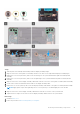
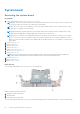
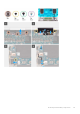
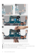
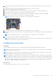
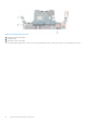
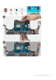
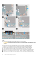
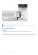
Table Of Contents
- Precision 5570 Service Manual
- Contents
- Working inside your computer
- Removing and installing components
- Drivers and downloads
- System setup
- Troubleshooting
- Handling swollen Lithium-ion batteries
- Locate the Service Tag or Express Service Code of your Dell computer
- System diagnostic lights
- SupportAssist diagnostics
- Built-in self-test (BIST)
- Recovering the operating system
- WiFi power cycle
- Drain residual flea power (perform hard reset)
- Backup media and recovery options
- Real Time Clock—RTC reset
- Getting help and contacting Dell
10. Replace the screw (M2x4) that secures the right Type-C bracket to the palm-rest and keyboard assembly.
11. Connect the fingerprint reader-board cable to the system board and close the latch to secure the cable.
12. Connect the right speaker cable to the system board.
13. Connect the keyboard cable to the system board and close the latch to secure the cable.
14. Thread the antenna cables through the clips on the system board and connect them to the wireless card.
15. Align the screw hole on the wireless-card bracket with the screw hole on the system board.
16. Replace the screw (M1.6x3) that secures the wireless-card bracket to the system board.
17. Connect the touch screen cable and camera cable to the display-assembly cable .
18. Replace the two screws (M1.6x3) that secure the display-assembly cable holder to the palm-rest and keyboard assembly.
19. Connect the touch screen cable and camera cable to the display-assembly cable.
20. Align the screw holes on the display-assembly cable bracket with the screw holes on the system board.
21. Tighten the three captive screws that secure the display-assembly cable bracket to the system board.
Next steps
1. Install the I/O board.
2. Install the right fan.
3. Install the left fan.
4. Install the heat sink.
5. Install the solid state drive 2.
6. Install the solid state drive 1.
7. Install the memory.
8. Install the battery.
9. Install the speakers.
10. Install the base cover.
11. Follow the procedure in After working inside your computer.
LED board
Removing the LED board
Prerequisites
1. Follow the procedure in Before working inside your computer.
2. Remove the base cover.
3. Remove the battery
4. Remove the speakers
About this task
The following images indicate the location of the LED board and provide a visual representation of the removal procedure.
Removing and installing components
49