Dell OptiPlex 9010/7010 Mini-Tower Owner's Manual Regulatory Model: D09M Regulatory Type: D09M003
Notes, Cautions, and Warnings NOTE: A NOTE indicates important information that helps you make better use of your computer. CAUTION: A CAUTION indicates either potential damage to hardware or loss of data and tells you how to avoid the problem. WARNING: A WARNING indicates a potential for property damage, personal injury, or death. © 2012 Dell Inc.
Contents Notes, Cautions, and Warnings...................................................................................................2 1 Working on Your Computer.......................................................................................................5 Before Working Inside Your Computer.....................................................................................................................5 Turning Off Your Computer...............................................................
Installing the Front Thermal Sensor........................................................................................................................26 Removing the Power Switch...................................................................................................................................26 Installing the Power Switch....................................................................................................................................
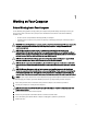
Working on Your Computer 1 Before Working Inside Your Computer Use the following safety guidelines to help protect your computer from potential damage and to help to ensure your personal safety. Unless otherwise noted, each procedure included in this document assumes that the following conditions exist: • You have read the safety information that shipped with your computer. • A component can be replaced or--if purchased separately--installed by performing the removal procedure in reverse order.
CAUTION: Before touching anything inside your computer, ground yourself by touching an unpainted metal surface, such as the metal at the back of the computer. While you work, periodically touch an unpainted metal surface to dissipate static electricity, which could harm internal components. Turning Off Your Computer CAUTION: To avoid losing data, save and close all open files and exit all open programs before you turn off your computer. 1.
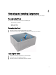
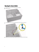
Removing and Installing Components 2 This section provides detailed information on how to remove or install the components from your computer. Recommended Tools The procedures in this document may require the following tools: • Small flat-blade screwdriver • Phillips screwdriver • Small plastic scribe Removing the Cover 1. Follow the procedures in Before Working Inside Your Computer. 2. Pull up the cover release latch, and lift the cover upwards to remove it from the computer.
Removing the Intrusion Switch 1. Follow the procedures in Before Working Inside Your Computer. 2. Remove the cover. 3. Press the clip inwards to release and gently pull the intrusion cable from system board. 4. Slide the intrusion switch toward the bottom of the chassis and remove it from the computer.
Installing the Intrusion Switch 1. Insert the intrusion switch into its place in the chassis rear and slide it towards the top to secure it. 2. Connect the intrusion cable to the system board. 3. Install the cover. 4. Follow the procedures in After Working Inside Your Computer. Removing the Front Bezel 1. Follow the procedures in Before Working Inside Your Computer. 2. Remove the cover. 3. Gently pry the front panel retention clips away from the chassis located at the edge of front panel.
4. Rotate the front panel away from the computer to release the hooks on the opposite edge of the panel from the chassis. Installing the Front Bezel 1. Insert the hooks along the bottom edge of the front panel into the slots on the chassis front. 2. Rotate the bezel toward the computer to engage the front-panel retention clips until they click into place. 3. Install the cover. 4. Follow the procedures in After Working Inside Your Computer. Removing the Expansion Cards 1.
3. Press the card-retention latch on the inside and pull the latch outwards on the other side. 4. Gently pull the release lever away from the PCIe x16 card until you release the securing tab from the dent in the card. Then, ease the card up and out of its connector and remove it from the system board.
5. Repeat step 4 to remove the other expansion card(s) if available. Installing the Expansion Card 1. Insert the expansion card into it's connector on the system board and press down until it is securely in place. 2. Repeat step 1 for other expansion cards (if available). 3. Install the cover. 4. Follow the procedures in After Working Inside Your Computer.
Installing the Memory 1. Align the notch on the memory-card with the tab in the system-board connector. 2. Press down on the memory module until the release tabs spring back to secure them in place. 3. Install the cover. 4. Follow the procedures in After Working Inside Your Computer. Removing the Coin-Cell Battery 1. Follow the procedures in Before Working Inside Your Computer. 2. Remove the cover. 3. Locate the coin-cell battery on the system board. 4. Remove the expansion card(s). 5.
Removing the Hard Drive 1. Follow the procedures in Before Working Inside Your Computer. 2. Remove the cover. 3. Remove the data cable and the power cable from the back of the hard drive. 4. Press both blue securing-bracket tabs inward and lift the hard-drive bracket out of the bay.
5. Flex the hard-drive bracket and then remove the hard drive from the bracket. 6. Repeat the steps 3 to 5 for the second hard drive, if available. Installing the Hard Drive 1. Insert the hard drive into the hard-drive bracket. 2. Press both blue securing-bracket tabs inward and slide the hard drive bracket into the bay in the chassis. 3. Connect the data cable and power cable to the back of the hard drive. 4. Install the cover. 5. Follow the procedures in After Working Inside Your Computer.
4. Remove the data cable and the power cable from the back of the optical drive. 5. Slide down and hold the optical drive latch to unlock the optical drive and pull the optical drive out of the computer.
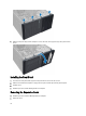
6. Repeat steps 4 to 5 to remove the second optical drive (if available). Installing the Optical Drive 1. Push the optical drive from the front toward the back of the computer till it is secured by the optical-drive latch. 2. Connect the data cable and power cable to the back of the optical drive. 3. Install the front panel. 4. Install the cover. 5. Follow the procedures in After Working Inside Your Computer. Removing the Speaker 1. Follow the procedures in Before Working Inside Your Computer.
4. Press down the speaker-securing tab and slide the speaker upwards to remove. Installing the Speaker 1. Slide the speaker downwards into its slot to secure it. 2. Thread the speaker cable into the chassis clip and connect the speaker cable to the system board. 3. Install the cover. 4. Follow the procedures in After Working Inside Your Computer. Removing the Power Supply 1. Follow the procedures in Before Working Inside Your Computer. 2. Remove the cover. 3.
4. Disconnect the power cable from the hard drive(s) and release it from the clip. Disconnect the 24–pin cable from the system board. 5. Disconnect the 4-pin power cable from the system board. 6. Remove the screws that secure the power supply to the back of the computer.
7. Push in on the blue release tab beside the power supply, and slide the power supply towards the front of the computer. 8. Lift the power supply out of the computer.
Installing the Power Supply 1. Place the power supply in the chassis and slide towards the back of the system to secure it. 2. Use a Phillips screwdriver to tighten the screws securing the power supply to the back of the computer. 3. Connect the 4-pin power cable to the system board. 4. Connect the 24-pin power cable to the system board. 5. Thread the power cables into the chassis clips. 6. Connect the power cables to the hard drive(s) and optical drive(s). 7. Install the cover. 8.
4. Use a Phillips screwdriver to loosen the captive screws in diagonal order and lift the heat sink away from the computer. Installing the Heat Sink 1. Place the heat sink into the chassis. 2. Use a Phillips screwdriver to tighten the captive screws in diagonal order to secure the heat sink to the system board. 3. Connect the heat sink cable to the system board. 4. Install the cover. 5. Follow the procedures in After Working Inside Your Computer.
Removing the Processor 1. Follow the procedures in Before Working Inside Your Computer. 2. Remove the cover. 3. Remove the heat sink. 4. Press the release lever down and then move it outward to release it from the retention hook. Lift the processor cover and remove the processor from the socket, and place it in antistatic bag. Installing the Processor 1. Insert the processor into the processor socket. Ensure the processor is properly seated. 2. Gently lower the processor cover. 3.
4. Pry and remove the system fan away from the four grommets securing it to the back of the computer. Installing the System Fan 1. Place the chassis fan in the chassis. 2. Pass the four grommets through the chassis and slide outward along the groove to secure in place. 3. Connect the fan cable to the system board. 4. Install the cover. 5. Follow the procedures in After Working Inside Your Computer. Removing the Thermal Sensor 1. Follow the procedures in Before Working Inside Your Computer. 2.
3. Disconnect the thermal sensor cable from the system board. 4. Release the thermal sensor cable from the chassis clip.
5. Gently press the tabs from both sides to release and remove the thermal sensor away from the chassis. Installing the Front Thermal Sensor 1. Gently secure the thermal sensor to the chassis. 2. Thread the thermal sensor cable into the chassis clips. 3. Connect the thermal sensor cable to the system board. 4. Install the cover. 5. Follow the procedures in After Working Inside Your Computer. Removing the Power Switch 1. Follow the procedures in Before Working Inside Your Computer. 2.
b) front bezel c) optical drive 3. Press in to release and remove the power-switch cable from the system board. 4. Release the power-switch cable from the chassis clips. 5. Press the clips on both side of the power switch to release it from the chassis and pull the power switch out of the computer.
6. Slide the power switch along with its cable out through the front of the computer. Installing the Power Switch 1. Slide the power switch in through the front of the computer. 2. Secure the power-switch cable to the chassis. 3. Thread the power-switch cable into the chassis clips. 4. Connect the power-switch cable to the system board. 5. Install the: a) optical drive b) front panel c) cover 6. Follow the procedures in After Working Inside Your Computer.
4. Disconnect the I/O panel and FlyWire cable from the system board. 5. Unthread and release the I/O Panel and FlyWire cable from the clip on the computer. 6. Remove the screw that secures the I/O panel to the computer.
7. Slide the I/O panel towards the left of the computer to release it and pull the I/O panel along with its cable out of the computer. Installing the Input/Output Panel 1. Insert the I/O panel into the slot on the chassis front. 2. Slide the I/O panel towards the right of the computer to secure to the chassis. 3. Use a Phillips screwdriver to tighten the single screw securing the I/O panel to the chassis. 4. Thread the I/O panel and FlyWire cables into the chassis clip. 5.
b) c) d) e) memory expansion card(s) heat sink processor 3. Disconnect all the cables connected to the system board. 4. Remove the screws that secure the system board to the computer. 5. Slide the system board towards the front of the computer.
6. 32 Carefully tilt the system board to 45–degrees, and then lift the system board out of the computer.
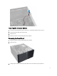
System Board Components Figure 1. Components Of The System Board 1. 2. 3. 4. 5. 6. 7. 8. 9. 10. 11. PCI Express x16 slot (wired as x4) PCI slot PCIe x1 slot Coin-cell battery PCI Express x16 slot Intrusion switch connector System fan connector 4–pin CPU power connecter CPU Socket Heat-sink fan connector DDR DIMM memory slots (4) 12. 13. 14. 15. 16. 17. 18. 19. 20. 21.
3. Connect the cables to the system board. 4. Install the: a) b) c) d) e) 5. 34 processor heat sink expansion card(s) memory cover Follow the procedures in After Working Inside Your Computer.
System Setup 3 System Setup enables you to manage your computer hardware and specify BIOS‐level options.
Keys Navigation Allows you to select a value in the selected field (if applicable) or follow the link in the field. Spacebar Expands or collapses a drop‐down list, if applicable. Moves to the next focus area. NOTE: For the standard graphics browser only. Moves to the previous page till you view the main screen. Pressing in the main screen displays a message that prompts you to save any unsaved changes and restarts the system. Displays the System Setup help file.
Table 3. System Configuration Option Description Integrated NIC Allows you to enable or disable the integrated network card. You can set the integrated NIC to: • • • • Disabled Enabled Enabled w/PXE Enabled w/ImageServer NOTE: Depending on the computer and its installed devices, the items listed in this section may or may not appear. Serial Port Allows you to define the serial port settings.
Option Description For Mini-Tower, Desktop, Small Form Factor the options are: • • • • Enable Boot Support Enable Rear Dual USB Ports Enable Rear Quad USB Ports Enable Front USB Ports For Ultra Small Form Factor, the options are: • • • • Enable Boot Support Enable Rear Dual USB 2.0 Ports Enable Rear Dual USB 3.0 Ports Enable Front USB Ports NOTE: USB keyboard and mouse always work in the BIOS setup irrespective of these settings.
Option Description • • • • Password Bypass Admin Password Min Admin Password Max System Password Min System Password Max Allows you to bypass the System Password and the internal HDD password prompts during a system restart. • • Disabled - Always prompt for the system and internal HDD password when they are set. This option is disabled by default. Reboot Bypass - Bypass the password prompts on restarts (warm boots).
Table 5. Performance Option Description Multi Core Support Specifies whether the process will have one or all cores enabled. The performance of some applications will improve with the additional cores. • • • Intel® SpeedStep™ C States Control Intel® TurboBoost™ Allows you to enable or disable the Intel SpeedStep mode of the processor. This option is enabled by default. Allows you to enable or disable the additional processor sleep states. This option is enabled by default.
Option Description This option is disabled by default. Fan Control Override Controls the speed of the system fan. This option is disabled by default. NOTE: When enabled, the fan runs at full speed. USB Wake Support This option allows you to enable USB devices to wake the computer from standby. • Wake on LAN Enable USB Wake Support - This option is disabled by default. This option allows the computer to power up from the off state when triggered by a special LAN signal.
Option Description • Trusted Execution Enable Intel Virtualization Technology for Direct I/O - This option is enabled by default. This option specifies whether a Measured Virtual Machine Monitor (MVMM) can utilize the additional hardware capabilities provided by Intel Trusted Execution technology. The TPM virtualization technology, and Virtualization technology for direct I/O must be enabled to use this feature. • Trusted Execution - This option is disabled by default. Table 9.
Option Description NOTE: This field is only relevant when the Integrated NIC control in the System Configuration group is set to Enabled with ImageServer and when Client DHCP is set to Static IP. Client SubnetMask Specifies the subnet mask of the client. The default setting is 255.255.255.255. NOTE: This field is only relevant when the Integrated NIC control in the System Configuration group is set to Enabled with ImageServer and when Client DHCP is set to Static IP.
Follow the instructions on the screen. Jumper Settings To change a jumper setting, pull the plug off its pin(s) and carefully fit it down onto the pin(s) indicated on the system board. The following table displays the system board jumper settings. Table 12. Jumper Settings Jumper Setting Description PSWD Default Password features are enabled RTCRST pin 1 and 2 Real-time clock reset. Can be used for troubleshooting.
4. Type the system password that you entered earlier and click OK. 5. Select Setup Password, type your system password and press or . A message prompts you to re-type the setup password. 6. Type the setup password that you entered earlier and click OK. 7. Press and a message prompts you to save the changes. 8. Press to save the changes. The computer reboots.
10. Install the cover. 11. Follow the procedures in After Working on Your Computer. 12. Power-on the computer. 13. Go to the system setup, and assign a new system or setup password. See Setting up a System Password.
Diagnostics 4 If you experience a problem with your computer, run the ePSA diagnostics before contacting Dell for technical assistance. The purpose of running diagnostics is to test your computer's hardware without requiring additional equipment or risking data loss. If you are unable to fix the problem yourself, service and support personnel can use the diagnostics results to help you solve the problem.
Troubleshooting Your Computer 5 You can troubleshoot your computer using indicators like Diagnostic Lights, Beep Codes, and Error Messages during the operation of the computer. Power LED Diagnostics The power button LED located on the front of the chassis also functions as a bicolored diagnostic LED. The diagnostic LED is only active and visible during the POST process. Once the operating system starts to load, it is no longer visible.
Amber LED State Description 3,7 some other failure with messages on screen Beep Code The computer can emit a series of beeps during start-up if the display does not show errors or problems. These series of beeps, called beep codes, identify various problems. The delay between each beep is 300 ms, the delay between each set of beeps is 3 sec, and the beep sound lasts 300 ms. After each beep and each set of beeps, the BIOS should detect if the user presses the power button.
Error Message Description Gate A20 failure One or more memory modules may be faulty or improperly seated. Reinstall the memory modules and, if necessary, replace them. General failure The operating system is unable to carry out the command. This message is usually followed by specific information—for example, Printer out of paper. Take the appropriate action to resolve the problem. Hard-disk drive configuration error The hard drive failed initialization.
Error Message Description Plug and play configuration error The computer encountered a problem while trying to configure one or more cards. Read fault The operating system cannot read from the floppy or hard drive, the computer could not find a particular sector on the disk, or the requested sector is defective. Requested sector not found The operating system cannot read from the floppy or hard drive, the computer could not find a particular sector on the disk, or the requested sector is defective.
6 Specifications NOTE: Offerings may vary by region. For more information regarding the configuration of your computer, click Start (Start icon) → Help and Support, and then select the option to view information about your computer. Table 14. Processor Feature Processor type Specification • • • • • Intel Core i3 series Intel Core i5 series Intel Core i7 series Intel Pentium Dual Core series Intel Celeron series NOTE: Intel Celeron series is only available for the Dell OptiPlex 7010.
Feature Specification • Discrete Intel HD Graphics 2500/4000 (i3/i5/i7 DC/QC Intel 7 Series Express Chipset CPU-GPU Combo) PCI Express x16 graphics adapter Table 17. Audio Feature Specification Integrated two Channel High Definition Audio Table 18. Network Feature Specification Integrated Intel 82579LM Ethernet capable of 10/100/1000 Mb/s communication Table 19.
Feature Specification PCI Express x1: Mini-Tower up to three full-height cards Desktop up to three low-profile cards Small Form Factor up to two low-profile cards Ultra Small Form Factor none PCI-Express x16: Mini-Tower up to two full-height cards Desktop up to two low-profile cards Small Form Factor up to two low-profile cards Ultra Small Form Factor none Mini PCI Express: Mini-Tower none Desktop none Small Form Factor none Ultra Small Form Factor up to one half-height card Table
Feature Specification Network Adapter one RJ45 connector Serial one 9-pin connector; 16550 C compatible Parallel one 25-pin connector (optional for mini-tower, desktop and small form factor) USB 2.0: Mini-Tower, Desktop, Small Form Factor Front Panel: 2 Back Panel: 4 Ultra Small Form Factor Front Panel: none Back Panel: 2 USB 3.
Feature Specification Mini-Tower four 7-pin connectors Desktop three 7-pin connectors Small Form Factor three 7-pin connectors Ultra Small Form Factor two 7-pin connectors Memory: Mini-Tower, Desktop, Small Form Factor four 240-pin connectors Ultra Small Form Factor two 240-pin connectors Internal USB: Mini-Tower and Desktop one 10-pin connector Small Form Factor and Ultra Small Form Factor none System Fan one 5-pin connector Front panel control: Mini-Tower, Desktop, Small Form Factor one
Feature Specification Link integrity light on integrated network adapter Green — a good 10 Mbps connection exists between the network and the computer. Orange — a good 100 Mbps connection exists between the network and the computer. Yellow — a good 1000 Mbps connection exists between the network and the computer. Off (no light) — the computer is not detecting a physical connection to the network.
Table 28. Environmental Feature Specification Temperature range: Operating 10 °C to 35 °C (50 °F to 95 °F) Storage –40 °C to 65 °C (–40 °F to 149 °F) Relative humidity (maximum): Operating 20% to 80% (non-condensing) Storage 5% to 95% (non-condensing) Maximum vibration: Operating 0.26 GRMS Storage 2.20 GRMS Maximum shock: Operating 40 G Storage 105 G Altitude: Operating –15.20 m to 3048 m (–50 ft to 10,000 ft) Storage –15.
Contacting Dell 7 To contact Dell for sales, technical support, or customer service issues: 1. Visit support.dell.com. 2. Verify your country or region in the Choose a Country/Region drop-down menu at the bottom of the page. 3. Click Contact Us on the left side of the page. 4. Select the appropriate service or support link based on your need. 5. Choose the method of contacting Dell that is convenient for you.