Dell OptiPlex 7020 Mini Tower Owner's Manual Regulatory Model: D13M Regulatory Type: D13M001
Notes, Cautions, and Warnings NOTE: A NOTE indicates important information that helps you make better use of your computer. CAUTION: A CAUTION indicates either potential damage to hardware or loss of data and tells you how to avoid the problem. WARNING: A WARNING indicates a potential for property damage, personal injury, or death. Copyright © 2014 Dell Inc. All rights reserved. This product is protected by U.S. and international copyright and intellectual property laws.
Contents 1 Working on Your Computer................................................................................5 Before Working Inside Your Computer................................................................................................ 5 Turning Off Your Computer..................................................................................................................6 After Working Inside Your Computer......................................................................................
Removing the Power Switch.............................................................................................................. 23 Installing the Power Switch................................................................................................................ 24 Removing the Input/Output (I/O) Panel.............................................................................................25 Installing the Input/Output (I/O) Panel..........................................................
Working on Your Computer 1 Before Working Inside Your Computer Use the following safety guidelines to help protect your computer from potential damage and to help to ensure your personal safety. Unless otherwise noted, each procedure included in this document assumes that the following conditions exist: • You have read the safety information that shipped with your computer. • A component can be replaced or--if purchased separately--installed by performing the removal procedure in reverse order.
To avoid damaging your computer, perform the following steps before you begin working inside the computer. 1. Ensure that your work surface is flat and clean to prevent the computer cover from being scratched. 2. Turn off your computer (see Turning Off Your Computer). CAUTION: To disconnect a network cable, first unplug the cable from your computer and then unplug the cable from the network device. 3. Disconnect all network cables from the computer. 4.
After Working Inside Your Computer After you complete any replacement procedure, ensure you connect any external devices, cards, and cables before turning on your computer. 1. Replace the cover. CAUTION: To connect a network cable, first plug the cable into the network device and then plug it into the computer. 2. Connect any telephone or network cables to your computer. 3. Connect your computer and all attached devices to their electrical outlets. 4. Turn on your computer. 5.
Removing and Installing Components This section provides detailed information on how to remove or install the components from your computer. Recommended Tools The procedures in this document may require the following tools: • Small flat-blade screwdriver • Phillips screwdriver • Small plastic scribe Removing the Cover 1. Follow the procedures in Before Working Inside Your Computer. 2. Pull up the cover release latch, and lift the cover upwards to remove it from the computer.
Removing the Intrusion Switch 1. Follow the procedures in Before Working Inside Your Computer. 2. Remove the cover. 3. Disconnect the intrusion-switch cable from the system board. 4. Slide the intrusion switch toward the bottom of the chassis and remove it from the computer. Installing the Intrusion Switch 1. Insert the intrusion switch into its place in the chassis rear and slide it towards the top to secure it. 2. Connect the intrusion cable to the system board. 3. Install the cover. 4.
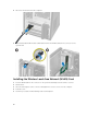
4. Disconnect the antenna from the computer. 5. Press the blue tab and lift the latch outwards and remove the WLAN card from the connector on the system board. Installing the Wireless Local Area Network (WLAN) Card 1. Insert the WLAN card into the connector on the system board and press down until it is secured. 2. Affix the latch. 3. Place the antenna puck on the connector and tighten the screws to secure it to the computer. 4. Install the cover. 5.
Removing the Front Bezel 1. Follow the procedures in Before Working Inside Your Computer. 2. Remove the cover. 3. Gently pry the front panel retention clips away from the chassis located at the edge of front panel. 4. Rotate the front panel away from the computer to release the hooks on the opposite edge of the panel from the chassis. Installing the Front Bezel 1. Insert the hooks along the bottom edge of the front bezel into the slots on the chassis front. 2.
3. Press the tab to release the latch. 4. Pull the release lever away from the PCI x16 card until you release the securing tab from the dent in the card. Lift the card out of its connector and remove it from the system board. Installing the Expansion Card 1. Insert the expansion card in the connector on the system board and press down until secured. 2. Push the retention latch back to its position. 3. Install the cover. 4. Follow the procedures in After Working Inside Your Computer.
• Memory modules of different sizes can be mixed (for example, 2 GB and 4 GB). But, all populated channels must have identical configurations. • Memory modules must be installed beginning with the first socket. NOTE: The memory sockets in your computer may be labeled differently depending on the hardware configuration. For example, A1, A2 or 1,2,3.
3. Locate the coin-cell battery on the system board. 4. Press the release latch away from the battery to allow the battery to pop-up from the socket and lift the coin-cell battery out of the computer. Installing the Coin-Cell Battery 1. Place the coin cell battery in its slot on the system board and press until the release latch springs back into place and secures it. 2. Install: a. expansion card b. cover 3. Follow the procedures in After Working Inside Your Computer. Removing the Hard Drive 1.
3. Disconnect the data cable and the power cable from the back of the hard drive. Press the blue securing-bracket tabs inwards and lift the hard-drive bracket out of the hard-drive bay. 4. Flex the hard-drive bracket and remove the hard drive from the hard-drive bracket. Installing the Hard Drive 1. Insert the hard drive into the hard-drive bracket. 2. Press the securing brackets inward and slide the hard-drive bracket into the bay. 3.
3. Disconnect the data cable and the power cable from the back of the optical drive. 4. Slide and hold the optical-drive latch to unlock the optical drive and pull the optical drive out of the computer. 5. Repeat steps 3 and 4 to remove the second optical drive (if available). Installing the Optical Drive 1. Push the optical drive from the front toward the back of the computer till it is secured by the opticaldrive latch. 2. Connect the data cable and power cable to the back of the optical drive.
4. Follow the procedures in After Working Inside Your Computer. Removing the Speaker 1. Follow the procedures in Before Working Inside Your Computer. 2. Remove the cover. 3. Disconnect and release the speaker cable from system board. Press down the speaker-securing tab and slide the speaker upwards to remove. Installing the Speaker 1. Slide the speaker downwards into its slot to secure it. 2. Thread the speaker cable into the chassis clip and connect the speaker cable to the system board. 3.
3. Disconnect the 4-pin and 8-in power cables from the system board and release the cable from the tab. 4. Remove the screws that secure the power supply to the back of the computer. 5. Push in on the blue release tab beside the power supply, and slide the power supply towards the front of the computer. Lift and remove the power supply out of the computer.
Installing the Power Supply 1. Place the power supply in the chassis and slide towards the back of the system to secure it. 2. Tighten the screws to secure the power supply to the back of the computer. 3. Connect the 4-pin and 8-pin power cables to the system board. 4. Thread the power cables through the chassis clips. 5. Install the cover. 6. Follow the procedures in After Working Inside Your Computer. Removing the Heat Sink Assembly 1.
3. Press the release lever down and then move it outward to release it from the retention hook. Lift the processor cover and remove the processor from the socket. Place it in an antistatic bag. Installing the Processor 1. Insert the processor in the processor socket. Ensure the processor is properly seated. 2. Lower the processor cover. 3. Press the release lever down and then move it inward to secure it with the retention hook. 4. Install: a. heat-sink assembly b. cover 5.
4. Pry and remove the system fan away from the four grommets securing it to the back of the computer. Installing the System Fan 1. Place the system fan in the chassis. 2. Pass the four grommets through the chassis and slide outward along the groove to secure in place. 3. Connect the system-fan cable to the system board. 4. Install the cover. 5. Follow the procedures in After Working Inside Your Computer. Removing the Thermal Sensor 1.
3. Disconnect the thermal-sensor cable from the system board. 4. Release the thermal-sensor cable from the chassis clip. 5. Press the tabs on both sides to release and remove the thermal sensor away from the chassis.
Installing the Thermal Sensor 1. Secure the thermal sensor to the chassis. 2. Thread the thermal-sensor cable into the chassis clips. 3. Connect the thermal-sensor cable to the system board. 4. Install the cover. 5. Follow the procedures in After Working Inside Your Computer. Removing the Power Switch 1. Follow the procedures in Before Working Inside Your Computer. 2. Remove the: a. cover b. front bezel c. optical drive 3. Disconnect the power-switch cable from the system board.
4. Release the power-switch cable from the chassis clips. 5. Press the clips on both side of the power switch to release it from the chassis and, slide to remove the power switch along its cable from the computer. Installing the Power Switch 1. Slide the power switch in through the front of the computer. 2. Secure the power-switch cable to the chassis. 3. Thread the power-switch cable into the chassis clips. 4. Connect the power-switch cable to the system board. 5. Install the: a.
Removing the Input/Output (I/O) Panel 1. Follow the procedures in Before Working Inside Your Computer. 2. Remove: a. cover b. front bezel 3. Disconnect the I/O panel, data, and USB data cables from the system board. 4. Unthread and release the I/O Panel, data cable and USB data cable from the clip on the computer. 5. Remove the screw that secures the I/O panel to the computer.
6. Slide the I/O panel towards the left of the computer to release it and pull the I/O panel along with its cable out of the computer. Installing the Input/Output (I/O) Panel 1. Insert the I/O panel into the slot on the chassis front. 2. Slide the I/O panel towards the right of the computer to secure to the chassis. 3. Tighten the screw to secure the I/O panel to the chassis. 4. Thread the I/O panel, data cable and USB data cable into the chassis clip. 5.
4. Remove the screws that secure the system board to the computer and slide the system board towards the front of the computer. 5. Tilt the system board at 45–degrees, and then lift the system board out of the computer. Installing the System Board 1. Align the system board to the port connectors on the rear of the chassis and place the system board in the chassis. 2. Tighten the screws securing the system board to the chassis. 3. Connect the cables to the system board. 4. Install the: a. b. c. d.
1. PCI Express x16 slot (wired as X4) 2. PCI slot 3. PCIe x1 slot 4. coin-cell battery 5. PCI Express x16 slot 6. intrusion switch connector 7. 4–pin CPU power connector 8. system fan connector 9. processor socket 10. heatsink fan connector 11. memory connectors ( SODIMM sockets) 12. front power-switch 13. 8–pin power connector 14. SATA connectors 15. HDD and optical drive power connector 16. SATA connectors 17. front panel USB connector 18. front panel audio connector 19.
System Setup 3 System Setup enables you to manage your computer hardware and specify BIOS‐level options.
Table 1. Navigation Keys Keys Navigation Up arrow Moves to the previous field. Down arrow Moves to the next field. Allows you to select a value in the selected field (if applicable) or follow the link in the field. Spacebar Expands or collapses a drop‐down list, if applicable. Moves to the next focus area. NOTE: For the standard graphics browser only. Moves to the previous page till you view the main screen.
Option Description Advance Boot Options Enable Legacy Option ROMs - This option is enabled by default. Date/Time Allows you to set the date and time. The changes to the system date and time takes effect immediately. Table 3. System Configuration Option Description Integrated NIC Allows you to enable or disable the integrated network card. You can set the integrated NIC to: • • • • • Enable UEFI Network Stack (disable by default) Disabled Enabled Enabled w/PXE- This option is enabled by default.
Option Description If USB port is disabled, the operation system cannot see any device attached to this port. USB configuration: For Mini-Tower, Small Form Factor the options are: • • • • • Enable Boot Support Enable Front USB 2.0 Ports Enable USB 3.0 Ports Enable Rear—Left Dual USB 2.0 Ports Enable Rear —Right Dual USB 2.0 Ports (default value is enable) NOTE: USB keyboard and mouse always work in the BIOS setup irrespective of these settings.
Option Description Password Change Allows you to determine whether changes to the system and hard disk passwords are permitted when an administrator password is set. • TPM Security Allow Non-Admin Password Changes - This option is enabled by default. This option lets you control whether the Trusted Platform Module (TPM) in the system is enabled and visible to the operating system. TPM Security - This option is disabled by default.
NOTE: To enable secure boot, UEFI boot mode must be enabled and Enable Legacy Option ROMs must be disabled or turned off. Expert key Management Allows you to manipulate the security key databases only if the system is in Custom Mode. The Enable Custom Mode option is disabled by default. The options are: • • • • PK KEK db dbx If you enable the Custom Mode, the relevant options for PK, KEK, db, and dbx appear.
Option Description • • Rapid Start Technology Disabled - Does not allow the TurboBoost driver to increase the performance state of the processor above the standard performance. Enabled - Allows the Intel TurboBoost driver to increase the performance of the CPU or graphics processor. Allows you to improve batter life by automatically putting the system into a low power status during after user specified amount of time.
Option Description USB Wake Support This option allows you to enable USB devices to wake the computer from standby. • Wake on LAN Enable USB Wake Support - This option is selected by default. This option allows the computer to power up from the off state when triggered by a special LAN signal. Wake-up from the Standby state is unaffected by this setting and must be enabled in the operating system. This feature only works when the computer is connected to AC power supply.
Option Description • Trusted Execution Enable Intel Virtualization Technology for Direct I/O - This option is enabled by default. This option specifies whether a Measured Virtual Machine Monitor (MVMM) can utilize the additional hardware capabilities provided by Intel Trusted Execution technology. The TPM virtualization technology, and Virtualization technology for direct I/O must be enabled to use this feature. • Trusted Execution - This option is disabled by default. Table 10.
Option Description NOTE: This field is only relevant when the Integrated NIC control in the System Configuration group is set to Enable with Cloud Desktop. Client IP Address Specifies the static IP address of the client. The default IP address is 255.255.255.255. NOTE: This field is only relevant when the Integrated NIC control in the System Configuration group is set to Enable with Cloud Desktop. Client SubnetMask Specifies the subnet mask of the client. The default setting is 255.255.255.255.
3. Enter the Service Tag or Express Service Code and click Submit. NOTE: To locate the Service Tag, click Where is my Service Tag? NOTE: If you cannot find your Service Tag, click Detect My Product. Proceed with the instructions on screen. 4. If you are unable to locate or find the Service Tag, click the Product Category of your computer. 5. Choose the Product Type from the list. 6. Select your computer model and the Product Support page of your computer appears. 7.
NOTE: Your computer is shipped with the system and setup password feature disabled. Assigning a System Password and Setup Password You can assign a new System Password and/or Setup Password or change an existing System Password and/or Setup Password only when Password Status is Unlocked. If the Password Status is Locked, you cannot change the System Password.
6. Press to save the changes and exit from the System Setup. The computer reboots. Disabling a System Password The system's software security features include a system password and a setup password. The password jumper disables any password(s) currently in use. NOTE: You can also use the following steps to disable a forgotten password. 1. Follow the procedures in Before Working on Your Computer. 2. Remove the cover. 3. Identify the PSWD jumper on the system board. 4.
Diagnostics 4 If you experience a problem with your computer, run the ePSA diagnostics before contacting Dell for technical assistance. The purpose of running diagnostics is to test your computer's hardware without requiring additional equipment or risking data loss. If you are unable to fix the problem yourself, service and support personnel can use the diagnostics results to help you solve the problem.
Troubleshooting Your Computer 5 You can troubleshoot your computer using indicators like Diagnostic Lights, Beep Codes, and Error Messages during the operation of the computer. Power LED Diagnostics The power button LED located on the front of the chassis also functions as a bicolored diagnostic LED. The diagnostic LED is only active and visible during the POST process. Once the operating system starts to load, it is no longer visible.
Amber LED State Description 3,5 memory modules are detected, but a memory configuration or compatibility error 3,6 possible system board resource and/or hardware failure 3,7 some other failure with messages on screen Beep Code The computer can emit a series of beeps during start-up if the display does not show errors or problems. These series of beeps, called beep codes, identify various problems.
Error Message Description Controller has failed The hard drive or the associated controller is defective. Data error The floppy or hard drive cannot read the data. For the Windows operating system, run the chkdsk utility to check the file structure of the floppy or hard drive. For any other operating system, run the appropriate corresponding utility. Decreasing available memory One or more memory modules may be faulty or improperly seated.
Error Message Description Memory allocation The software you are attempting to run is conflicting with the operating system, error another program, or a utility. Memory data line failure at address, read value expecting value A memory module may be faulty or improperly seated. Reinstall the memory modules and, if necessary, replace them. Memory double word logic failure at address, read value expecting value A memory module may be faulty or improperly seated.
Error Message Description Reset failed The disk re-set operation failed. Sector not found The operating system cannot locate a sector on the floppy or hard drive. Seek error The operating system cannot find a specific track on the floppy disk or hard drive. Shutdown failure A chip on the system board might be malfunctioning. Time-of-day clock The battery might be dead.
6 Specifications NOTE: Offerings may vary by region. For more information regarding the configuration of your computer, click Start (Start icon) → Help and Support, and then select the option to view information about your computer. Table 15. Processor Feature Specification Processor type • Intel Core i3/i5/i7 series • Intel Dual Core series Total Cache Up to 8 MB cache depending on processor type Table 16.
Table 19. Network Feature Specification Integrated Intel I217LM Ethernet capable of 10/100/1000 Mb/s communication Table 20. System Information Feature Specification System chipset Intel 8 series Express chipset DMA Channels two 8237 DMA controllers with seven independently programmable channels Interrupt Levels Integrated I/O APIC capability with 24 interrupts BIOS Chip (NVRAM) 12 MB Table 21. Expansion Bus Feature Specification Bus Type PCIe gen2, gen3 (x16), USB 2.0, and USB 3.
Feature Small Form Factor Internally Accessible Specification one slim-optical drive bay 3.5-inch SATA drive bays 2.5-inch SATA drive bays Mini-Tower two two Small Form Factor one two Table 24.
Feature Specification Mini-Tower one 164-pin connector Small Form Factor one 64–pin connector PCI Express x16 data width (maximum) — 16 PCI Express lanes Mini-Tower, Small Form Factor one 164-pin connector Mini PCI Express data width (maximum) — one PCI Express lane and one USB interface Mini-Tower, Small Form Factor none Serial ATA: Mini-Tower four 7-pin connectors Small Form Factor three 7-pin connectors Memory: Mini-Tower, Small Form Factor four 240-pin connectors Internal USB: Mini-Tower
Table 26. Controls and Lights Feature Specification Front of the computer: Power button light White light — Solid white light indicates power-on state; blinking white light indicates sleep state of the computer. Drive activity light White light — Blinking white light indicates that the computer is reading data from or writing data to the hard drive. Back of the computer: Link integrity light on integrated network Green — a good 10 Mbps connection exists between the adapter network and the computer.
Table 28. Physical Dimension Physical Height Width Depth Weight Mini-Tower 36.00 cm (14.17 inches) 17.50 cm (6.89 inches) 41.70 cm (16.42 inches) 9.40 kg (20.72 lb) Small Form Factor 29.00 cm (11.42 inches) 9.30 cm (3.66 inches) 31.20 cm (12.28 inches) 6.00 kg (13.22 lb) Table 29.
Contacting Dell 7 NOTE: If you do not have an active Internet connection, you can find contact information on your purchase invoice, packing slip, bill, or Dell product catalog. Dell provides several online and telephone-based support and service options. Availability varies by country and product, and some services may not be available in your area. To contact Dell for sales, technical support, or customer service issues: 1. Go to dell.com/contactdell. 2.