
Service Manual
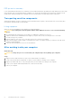

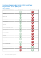
Table Of Contents
- OptiPlex 3000 Small Form Factor Service Manual
- Contents
- Working inside your computer
- Removing and installing components
- Recommended tools
- Screw list
- Customer Replaceable Units (CRU) and Field Replaceable Units (FRU) list
- Major components of OptiPlex 3000 Small Form Factor
- Side cover
- Front bezel
- Intrusion switch
- Hard drive
- Disk-drive cage
- Optical drive
- Solid-state drive
- Bay-support bracket
- Coin-cell battery
- Power button
- WLAN card
- WLAN antenna
- WLAN antennas (External)
- Memory
- Processor fan and heat-sink assembly
- Processor
- Expansion card
- Optional I/O modules (PS2/Serial)
- Optional I/O modules (VGA/HDMI/DP)
- Speakers
- Power-supply unit
- System board
- Drivers and downloads
- Getting help and contacting Dell

Removing and installing components
NOTE: The images in this document may differ from your computer depending on the configuration you ordered.
Recommended tools
The procedures in this document may require the following tools:
● Phillips screwdriver #0
● Phillips screwdriver #1
● Torx #5 (T5) screwdriver
● Plastic scribe
Screw list
NOTE: When removing screws from a component, it is recommended to note the screw type, the quantity of screws, and
then place them in a screw storage box. This is to ensure that the correct number of screws and correct screw type is
restored when the component is replaced.
NOTE: Some computers have magnetic surfaces. Ensure that the screws are not left attached to such surfaces when
replacing a component.
NOTE: Screw color may vary with the configuration ordered.
Table 1. Screw list
Component Screw type Quantity Screw image
Solid-state drive M2x3 1
Hard-drive and optical-drive
supporting bracket
#6-32 2
SD-card reader M3x5 1
WLAN card M2x3 1
Processor-fan and heat-sink
assembly
Captive 4
Power-supply unit #6-32 3
System board #6-32 7
2
Removing and installing components 9