
Service Manual
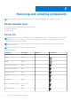
Table Of Contents
- Latitude 5430 Service Manual
- Contents
- Working inside your computer
- Removing and installing components
- Recommended tools
- Screw list
- Major components of Latitude 5430
- SIM card tray
- MicroSD card
- Base cover
- WLAN card
- WWAN card
- Solid-state drive
- Memory modules
- Battery
- Battery cable
- Assembly inner frame
- LED board
- Heat sink
- Speakers
- System board
- Power-button board
- Smart card reader
- Keyboard assembly
- Display assembly
- Display bezel
- Display panel
- Camera/microphone module
- eDP/display cable
- Sensor board
- Display hinges
- Display back cover
- Palm-rest assembly
- Dummy SIM-card slot filler
- Drivers and downloads
- BIOS setup
- Troubleshooting
- Handling swollen Lithium-ion batteries
- Dell SupportAssist Pre-boot System Performance Check diagnostics
- Built-in self-test (BIST)
- System-diagnostic lights
- Recovering the operating system
- Real-Time Clock (RTC Reset)
- Auto RTC reset
- Backup media and recovery options
- WiFi power cycle
- Drain residual flea power (perform hard reset)
- Getting help and contacting Dell

Removing and installing components
NOTE: The images in this document may differ from your computer depending on the configuration you ordered.
Recommended tools
The procedures in this document may require the following tools:
● Phillips screwdriver #0
● Plastic scribe
Screw list
NOTE: When removing screws from a component, it is recommended to note the screw type, the quantity of screws, and
then place them in a screw storage box. This is to ensure that the correct number of screws and correct screw type is
restored when the component is replaced.
NOTE: Some computers have magnetic surfaces. Ensure that the screws are not left attached to such surfaces when
replacing a component.
NOTE: Screw color may vary with the configuration ordered.
Table 1. Screw list
Component Screw type Quantity Screw image
Base cover Captive screw 8
N/A
WLAN M2x2.5 1
WWAN M2x2.5 1
M.2 2230 solid-state drive M2x3 4
M.2 2280 solid-state drive M2x3 2
Assembly inner frame M2x3 10
3-cell battery M2x5 3
4-cell battery M2x5 3
Heat-sink assembly-integrated Captive screw
M2x5
4
2
eDP cable/bracket M2x3 2
2
10 Removing and installing components