Dell OptiPlex 9020 AIO Owner's Manual Regulatory Model: W04C Regulatory Type: W04C002
Notes, Cautions, and Warnings NOTE: A NOTE indicates important information that helps you make better use of your computer. CAUTION: A CAUTION indicates either potential damage to hardware or loss of data and tells you how to avoid the problem. WARNING: A WARNING indicates a potential for property damage, personal injury, or death. © 2013 Dell Inc. All Rights Reserved.
Contents 1 Working on Your Computer....................................................................................................... 5 Before Working Inside Your Computer.....................................................................................................................5 Recommended Tools................................................................................................................................................ 6 Turning Off Your Computer............................
Installing the Power-Supply Fan.............................................................................................................................25 Removing the I/O Board Shield...............................................................................................................................26 Installing the I/O Board Shield................................................................................................................................
Working on Your Computer 1 Before Working Inside Your Computer Use the following safety guidelines to help protect your computer from potential damage and to help to ensure your personal safety. Unless otherwise noted, each procedure included in this document assumes that the following conditions exist: • You have read the safety information that shipped with your computer. • A component can be replaced or--if purchased separately--installed by performing the removal procedure in reverse order.
CAUTION: Before touching anything inside your computer, ground yourself by touching an unpainted metal surface, such as the metal at the back of the computer. While you work, periodically touch an unpainted metal surface to dissipate static electricity, which could harm internal components.
After Working Inside Your Computer After you complete any replacement procedure, ensure you connect any external devices, cards, and cables before turning on your computer. 1. Replace the cover. CAUTION: To connect a network cable, first plug the cable into the network device and then plug it into the computer. 2. Connect any telephone or network cables to your computer. 3. Connect your computer and all attached devices to their electrical outlets. 4. Turn on your computer. 5.
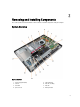
Removing and Installing Components 2 This section provides detailed information on how to remove or install the components from your computer. System Overview Figure 1. Inside View 1. 2. 3. 4. power supply unit (PSU) camera hard drive processor fan 5. 6. 7. 8.
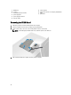
9. 10. 11. 12. 13. 14. WLAN card speakers input/output (I/O) board shield power-supply fan power-supply fan bracket intrusion switch 15. converter board 16. power-button and on-screen display (OSD) buttons board 17. optical drive Removing the VESA Stand 1. Follow the procedures in Before Working Inside Your Computer. 2. Place the computer on a flat surface, display side facing downwards. 3. Using a plastic scribe, release the cover starting with the notches at the bottom.
5. Remove the screws that secure the VESA stand to the computer and lift the VESA stand away from the computer. Installing the VESA Stand 1. Align and place the VESA stand on the back of the computer. 2. Tighten the screws that secure the VESA stand to the computer. 3. Place and press the VESA cover on the computer, until it clicks into place. 4. Follow the procedures in After Working Inside Your Computer. Removing the Back Cover 1. Follow the procedures in Before Working Inside Your Computer.
4. Lift the cover and remove it from the computer using the notches near the input/output (I/O) panel. Installing the Back Cover 1. Align the back cover to its original position on the computer and press until it clicks in place. 2. Tighten the screws to secure the back cover to the computer. 3. Install the VESA stand. 4. Follow the procedures in After Working Inside Your Computer. Removing the Memory 1. Follow the procedures in Before Working Inside Your Computer. 2.
3. Lift the memory shield outwards. 4. Pry the retention clips away from the memory module until it pops-up. Lift and remove the memory module from its connector. Installing the Memory 1. Align the notch on the memory-card with the tab in the system-board connector. 2. Press down on the memory module until the release tabs spring back to secure them in place. 3. Place the memory shield back into its place. 4. Install the: a) back cover b) VESA stand 5.
Installing the VESA Mount Bracket 1. Align and place the bracket on the back of the computer. 2. Tighten the screws that secure the VESA mount bracket to the computer. 3. Install the: a) back cover b) VESA stand 4. Follow the procedures in After Working Inside Your Computer. Removing the Power and On-Screen Display (OSD) Buttons Board 1. Follow the procedures in Before Working Inside Your Computer. 2. Remove the: a) VESA stand b) back cover 3.
Installing the Power and OSD Buttons Board 1. Align and place the power and OSD buttons board on the computer. 2. Connect the cable to the power and OSD buttons board. 3. Install: a) back cover b) VESA stand 4. Follow the procedures in After Working Inside Your Computer. Removing the System-Board Shield 1. Follow the procedures in Before Working Inside Your Computer. 2. Remove the: a) VESA stand b) back cover c) VESA mount bracket 3.
Installing the System-Board Shield 1. Align and place the system-board shield on the back of the computer. 2. Tighten the screws that secure the system-board shield to the computer. 3. Install the: a) VESA mount bracket b) back cover c) VESA stand 4. Follow the procedures in After Working Inside Your Computer. Removing the Converter Board 1. Follow the procedures in Before Working Inside Your Computer. 2. Remove the: a) VESA stand b) back cover 3.
Installing the Converter Board 1. Place the convertor board into its place. 2. Tighten the screws to secure the converter board to the computer. 3. Connect the backlight and converter cables to the converter board. 4. Install the: a) back cover b) VESA stand 5. Follow the procedures in After Working Inside Your Computer. Removing the Coin-Cell Battery 1. Follow the procedures in Before Working Inside Your Computer. 2. Remove the: a) VESA stand b) back cover c) system-board shield 3.
4. Slide the optical drive outward and disconnect the optical-drive cable. 5. Slide and lift the optical drive from the computer. 6. Remove the screws that secure the optical-drive bracket to the optical drive. Remove the optical-drive bracket from the optical drive.
Installing the Optical Drive 1. Place the optical-drive bracket on the optical drive. 2. Tighten the screws that secure the optical-drive bracket to the optical drive. 3. Align and slide the optical drive into its slot. 4. Connect the optical-drive cable. 5. Tighten the screws that secure the optical drive to the computer. 6. Install the: a) back cover b) VESA stand 7. Follow the procedures in After Working Inside Your Computer. Removing the Hard Drive 1.
5. For a 2.5–inch hard drive, remove the screws that secure the hard drive to the hard-drive bracket. Slide the hard drive from the hard-drive bracket. Remove the screws that secure the hard-drive case to the hard drive. 6. For a 3.5–inch hard drive, remove the screws that secure the hard drive to the hard-drive bracket. Slide the hard drive from the hard-drive bracket. Installing the Hard Drive 1. For a 3.5–inch hard drive, slide the hard drive into the hard-drive bracket. 2. For a 2.
c) VESA stand 7. Follow the procedures in After Working Inside Your Computer. Removing the Intrusion Switch 1. Follow the procedures in Before Working Inside Your Computer. 2. Remove the: a) b) c) d) VESA stand back cover VESA mount bracket system-board shield 3. Disconnect the intrusion-switch cable from the connector on the system board. Unthread the cable from the notches on the computer. 4. Remove the screws that secure the intrusion switch to the chassis.
Installing the Intrusion Switch 1. Place the intrusion switch on the computer and tighten the screw to secure it to the chassis. 2. Thread the cable along the notches on the chassis and connect the intrusion-switch cable to the connector on the system board. 3. Install: a) b) c) d) 4. system-board shield VESA mount bracket back cover VESA stand Follow the procedures in After Working Inside Your Computer. Removing the Wireless Local Area Network (WLAN) Card 1.
Installing the WLAN Card 1. Align and place the WLAN card on the WLAN adapter. Tighten the screws to secure the WLAN card to the WLAN adapter 2. Place the WLAN card along with the WLAN adapter on its connector and tighten the screws to secure the WLAN card to the system board. 3. Connect the WLAN cables. 4. Install: a) b) c) d) 5. system-board shield VESA mount bracket back cover VESA stand Follow the procedures in After Working Inside Your Computer. Removing the Heat-Sink Assembly 1.
d) VESA stand 4. Follow the procedures in After Working Inside Your Computer. Removing the Processor Fan 1. Follow the procedures in Before Working Inside Your Computer. 2. Remove the: a) b) c) d) 3. VESA stand back cover VESA mount bracket system-board shield Disconnect the processor-fan cable from the connector on the system board. Remove the screws that secure the processor fan to the system board and lift it away from the computer. Installing the Processor Fan 1.
4. Remove the screws that secure the power-supply fan to the chassis and lift it away from the computer. Installing the Power-Supply Fan 1. Place the power-supply fan on the computer and tighten the screws to secure it to the chassis. 2. Align and place the fan duct from the computer. 3. Tighten the screw that secures the fan duct to the chassis. 4. Install: a) b) c) d) 5. system-board shield VESA mount bracket back cover VESA stand Follow the procedures in After Working Inside Your Computer.
Removing the I/O Board Shield 1. Follow the procedures in Before Working Inside Your Computer. 2. Remove the: a) b) c) d) e) VESA stand back cover VESA mount bracket power supply fan system-board shield 3. Lift the I/O panel away from the computer. 4. Remove the screws that secure the power connector to the I/O board shield. 5. Remove the screws that secure the I/O board shield to the chassis. Loosen the power connector and press it down the socket.
6. Flip the input/output (I/O) board shield and remove it from the computer. 7. Disconnect the power-connector cable from the system board.
Installing the I/O Board Shield 1. Connect the power-connector cable to the system board. 2. Place the I/O board shield on the computer. 3. Pass the power connector and fix it to the socket. Tighten the screws that secure the I/O board shield to the chassis. 4. Tighten the screws that secure the power connector to the I/O shield. 5. Place the I/O panel on the computer. 6. Install: a) b) c) d) e) 7.
4. Remove the screws that secure the PSU to the chassis. Lift the PSU up and remove it from the computer. Installing the Power Supply Unit 1. Place the power supply unit on the computer. 2. Tighten the screws to secure the power supply unit to the chassis. 3. Thread the cable on the hooks in the computer. 4. Connect the power-supply cables to the connector on the system board. 5.
6. Follow the procedures in After Working Inside Your Computer. Removing the Processor 1. Follow the procedures in Before Working Inside Your Computer. 2. Remove the: a) b) c) d) e) 3. VESA stand back cover VESA mount bracket system-board shield heat-sink assembly Press the release lever down and then move it outward to release it from the retention hook that secures it. Lift the processor cover and remove the processor from its socket. Installing the Processor 1.
4. Remove the screws that secure the speakers to the chassis. Lift the speakers from the computer. Installing the Speakers 1. Place and align the speakers on the chassis. Tighten the screws that secure the speaker to the chassis. 2. Thread the cables on the notches. Connect the speaker cables to the system board. 3. Install: a) b) c) d) 4. system-board shield VESA mount bracket back cover VESA stand Follow the procedures in After Working Inside Your Computer.
Removing the System Board 1. Follow the procedures in Before Working Inside Your Computer. 2. Remove the: a) b) c) d) e) f) g) h) i) j) k) l) VESA stand back cover VESA mount bracket system-board shield memory optical drive hard drive heat-sink assembly power supply unit input/output (I/O) board shield converter board power-supply fan 3. Disconnect all the cables that are connected to the system board. 4. Remove the screws that secure the system board to the computer. 5.
1. SATA ODD power connector 2. SATA HDD connector 3. SATA HDD power connector 4. SATA ODD connector 5. graphic heat sink fan connector 6. intrusion switch connector 7. processor heat sink fan connector 8. camera connector 9. coin-cell battery connector 10. processor socket 11. memory connectors (SODIMM sockets) 12. speaker connector 13. mini-PCI Express socket 14. 12V CPU power connector 15. LVDS Connector 16. convertor board connector 17. touch panel connector 18. front panel connector 19.
20. 8–pin power connector Installing the System Board 1. Place the system board on the computer. 2. Connect all the cables to the system board. 3. Tighten the screws to secure the system board to the base panel. 4. Install: a) b) c) d) e) f) g) h) i) j) k) l) 5.
4. Press and push down the screws that are connected to the system board. 5. Remove the heat sink from the system board. Installing the Heat Sink (Graphics Card) 1. Place the heat sink on the system board. 2. Press the screws to lock the heat sink to its position. 3. Connect the fan cable. 4.
d) e) f) g) h) i) j) k) l) m) 5. input/output (I/O) board shield power supply unit heat-sink assembly hard drive optical drive memory system-board shield VESA mount bracket back cover VESA stand Follow the procedures in After Working Inside Your Computer. Removing the Antenna Module 1. Follow the procedures in Before Working Inside Your Computer. 2. Remove the: a) b) c) d) e) f) g) h) i) j) k) l) m) n) o) p) 3.
Installing the Antenna Module 1. Place the antenna module on the chassis. 2. Thread the antenna cable around the edges of the computer. Tighten the screws to secure the antenna module to the chassis 3. Install: a) b) c) d) e) f) g) h) i) j) k) l) m) n) o) p) 4.
NOTE: These instructions are valid only for non-touch computers. For touch computers, the display panel should be disassembled in a clean-room environment. 3. Disconnect the LVDS cable from the display panel. Remove any other cables or antennae around the edges of the base panel. 4. Remove the screws that secure the base panel to the chassis. Lift the base panel from the chassis. 5. Lift the display panel from the chassis.
6. Remove the screws that secure the display bracket to the display panel. Remove the display bracket from the display panel. Installing the Display Panel 1. Tighten the screws to secure the display bracket to the display panel. 2. Place the display panel on the chassis. 3. Place the base panel on the chassis. 4. Tighten the screws to secure the base panel to the chassis. 5. Connect the LVDS cable to the display panel. 6.
f) g) h) i) j) k) l) m) n) o) p) q) r) 7. power supply unit power-supply fan converter board power and OSD buttons board intrusion switch hard drive optical drive WLAN card input/output (I/O) board shield system-board shield VESA mount bracket back cover VESA stand Follow the procedures in After Working Inside Your Computer. Removing the Camera 1. Follow the procedures in Before Working Inside Your Computer. 2. Remove the: a) b) c) d) e) f) g) h) i) j) k) l) m) n) o) p) q) 3.
Installing the Camera 1. Tighten the screws to secure the camera to the chassis. 2. Connect the camera cable and fix the latch. 3. Install: a) b) c) d) e) f) g) h) i) j) k) l) m) n) o) p) q) 4.
System Setup 3 System Setup enables you to manage your computer hardware and specify BIOS‐level options.
Keys Navigation Allows you to select a value in the selected field (if applicable) or follow the link in the field. Spacebar Expands or collapses a drop‐down list, if applicable. Moves to the next focus area. NOTE: For the standard graphics browser only. Moves to the previous page till you view the main screen. Pressing in the main screen displays a message that prompts you to save any unsaved changes and restarts the system. Displays the System Setup help file.
Option Description • • • • Advanced Boot Options The Enable Legacy Option ROMs option will allow the legacy option ROMs to load, when in UEFI boot mode. Without this option, only UEFI option ROMs will load. This option is required for Legacy boot mode. This Legacy boot mode is not allowed when you enable the Secure Boot. By default, the Enable Legacy Option ROMs check-box is not selected. The other options are: • • • Date/Time View - Enables you to view the current boot option in the computer.
Option Description USB Configuration This field configures the integrated USB controller. If Boot Support is enabled, the system is allowed to boot any type of USB mass storage devices (HDD, memory key, floppy). If USB port is enabled, device attached to this port is enabled and available for operation system. If USB port is disabled, the operation system cannot see any device attached to this port. NOTE: USB keyboard and mouse always work in the BIOS setup irrespective of these settings.
Option Description The drive does not have a password set by default. • • • Internal HDD-4 Password Enter the old password Enter the new password Confirm the new password Allows you to set, change, or delete the password on the computer's internal hard disk drive (HDD). Successful changes to this password take effect immediately. The drive does not have a password set by default.
Option Description • • • CPU XD Support Allows you to enable or disable the execute disable mode of the processor. • OROM Keyboard Access Disable Enable - This option is enabled by default On-Silent Enable CPU XD Support - This option is enabled by default. Allows you to determine if you access the Option Read Only Memory (OROM) configuration screens via hotkeys during boot. These settings prenvent access to the Intel RAID (CTRL+I) or Intel Management Engine BIOS Extension (CTRL+P/F12).
Option Description • • • • Append from File- Adds a key to the current database from a user-selected file Delete- Deletes the selected key Reset All Keys- Resets to default setting Delete All Keys- Deletes all the keys NOTE: If you disable the Custom Mode, all the changes made will be erased and the keys will restore to default settings. Table 6. Performance Option Description Multi Core Support Specifies whether the process will have one or all cores enabled.
Option Description • • Auto On Time Power On Last Power State This option sets the time of the day when you would like the system to turn on automatically. Time is kept in standard 12-hour format (hour:minutes:seconds). The startup time can be changed by typing the values in the time and A.M./P.M. fields. • • • • Disabled - The system will not automatically power up. Every Day - The system will power up every day at the time you specified above .
Table 8. POST Behavior Option Description Numlock LED Specifies if the NumLock function can be enabled when the system boots. This option is enabled by default. Keyboard Errors Specifies whether keyboard related errors are reported when it boots. This option is enabled by default. POST Hotkeys Specifies whether the sign-on screen displays a message, that displays the keystroke sequence required to enter the BIOS Boot Option Menu.
Table 11. Maintenance Option Description Service Tag Displays the service tag of your computer. Asset Tag Allows you to create a system asset tag if an asset tag is not already set. This option is not set by default. SERR Messages Controls the SERR message mechanism. This option is not set by default. Some graphics cards require that the SERR message mechanism be disabled. Table 12.
Option Description NOTE: This option is relevant only when the Integrated NIC control in the System Configuration group is set to Enable with Cloud Desktop. Advanced This option turns on the Verbose Mode for advanced debugging. By default, this option is not enabled. NOTE: This option is relevant only when the Integrated NIC control in the System Configuration group is set to Enable with Cloud Desktop. Table 13.
Password Type Description System password Password that you must enter to log on to your system. Setup password Password that you must enter to access and make changes to the BIOS settings of your computer. CAUTION: The password features provide a basic level of security for the data on your computer. CAUTION: Anyone can access the data stored on your computer if it is not locked and left unattended. NOTE: Your computer is shipped with the system and setup password feature disabled.
To enter the System Setup, press immediately after a power-on or reboot. 1. In the System BIOS or System Setup screen, select System Security and press . The System Security screen is displayed. 2. In the System Security screen, verify that Password Status is Unlocked. 3. Select System Password, alter or delete the existing system password and press or . 4. Select Setup Password, alter or delete the existing setup password and press or .
4 Technical Specifications NOTE: Offerings may vary by region. For more information regarding the configuration of your computer, click Start (Start icon) → Help and Support, and then select the option to view information about your computer. Table 14. System Information Feature Processor type Specification • • Intel Dual / Quad Core Intel Core i3 / i5 / i7 series Total cache Up to 8 MB cache depending on processor type Chipset Intel Q87 Express chipset Table 15.
Table 17. Audio Feature Specification Controller Intel High Definition Audio with Waves MaxxVoice Pro Speaker single 8-ohms speakers in both the left and right speaker assembly (5 W average per channel) Internal speaker amplifier up to 15 W per channel Internal microphone support dual digital microphone Volume controls Volume up/down buttons (Windows 7 only), program menus, and keyboard media-control keys Table 18.
Table 22. Ports and Connectors Feature Specification Audio: • • • one line-out connector one audio input/microphone port one headphone port Network adapter one RJ45 connector USB 2.0 four USB 3.0 four Video 15-pin VGA connector HDMI one 19-pin output port Media card reader one 8-in-1 slot Table 23. Power Feature Specification 200 Watt PSU Frequency 50 Hz — 60 Hz Voltage 100 VAC — 240 VAC Input current Maximum 2.90 A Maximum 1.
Feature Without Stand With Stand non-touch 70.50 mm (2.78 inches) 174.40 mm (6.87 inches) touch 72.80 mm (2.87 inches) 174.40 mm (6.87 inches) Weight: non-touch 8.10 kg to 8.76 kg (17.86 lb to 10.25 kg to 10.91 kg (22.60 lb to 24.05 lb) 19.31 lb) touch 9.19 kg to 9.84 kg (20.26 lb to 11.34 kg to 11.99 kg (25.00 lb to 26.43 lb) 21.70 lb) NOTE: The weight of your computer may vary depending on the configuration ordered and the manufacturing variability. Table 27.
Feature Specification Relative humidity (maximum): Operating 10% to 90% (non-condensing) Storage 10% to 95% (non-condensing) Maximum vibration: Operating 0.66 GRMS Storage 1.30 GRMS Maximum shock: Operating 110 G Storage 160 G Altitude: Operating –15.2 m to 3048 m (–50 to 10,000 ft) Storage –15.20 m to 10,668 m (–50 ft to 35,000 ft) Airborne contaminant level G2 or lower as defined by ANSI/ISA-S71.
Contacting Dell 5 NOTE: If you do not have an active Internet connection, you can find contact information on your purchase invoice, packing slip, bill, or Dell product catalog. Dell provides several online and telephone-based support and service options. Availability varies by country and product, and some services may not be available in your area. To contact Dell for sales, technical support, or customer service issues: 1. Visit dell.com/support 2. Select your support category. 3.