Dell™ OptiPlex™ 960 Service Manual Mini Tower Computer Desktop Computer Small Form Factor Computer
Back to Contents Page Battery Dell™ Optiplex™ 960 Mini Tower/Desktop/Small Form Factor Service Manual Replacing the Battery Replacing the Battery CAUTION: Before you begin any of the procedures in this section, read the safety information that shipped with your computer. For additional safety best practices information, see the Regulatory Compliance Homepage at www.dell.com/regulatory_compliance.
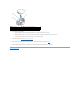
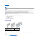
1 system battery 2 positive side of battery connector 3 battery socket tab 4 battery socket 6. Install the new system battery. a. Support the battery connector by pressing down firmly on the positive side of the connector. b. Hold the battery with the "+" facing up, and slide it under the securing tabs at the positive side of the connector. c. Press the battery straight down into the connector until it snaps into place. 7. Perform the procedure After Working on Your Computer. 8.
Back to Contents Page Contacting Dell Dell™ Optiplex™ 960 Mini Tower/Desktop/Small Form Factor Service Manual To contact Dell for sales, technical support, or customer service issues: 1. Visit support.dell.com. 2. Verify your country or region in the Choose a Country/Region drop-down menu at the bottom of the page. 3. Click Contact Us on the left side of the page. 4. Select the appropriate service or support link based on your need. 5.
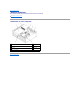
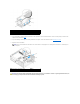
Back to Contents Page Desktop Computer Dell™ Optiplex™ 960 Mini Tower/Desktop/Small Form Factor Service Manual Inside View of Your Computer Inside View of Your Computer 1 drive bays (media card reader, floppy drive, optical drive, hard drive(s)) 2 power supply 3 chassis-intrusion switch 4 system board 5 card slots 6 heatsink assembly 7 front I/O assembly Back to Contents Page
Dell™ OptiPlex™ 960 Service Manual Desktop Computer Working on Your Computer Inside View of Your Computer System Board Components Cover Chassis Intrusion Switch Cards Drives Processor I/O Panel Power Supply Speakers Battery System Board Memory Troubleshooting Tips Contacting Dell Notes, Notices, and Cautions NOTE: A NOTE indicates important information that helps you make better use of your computer.
Back to Contents Page Dell™ Optiplex™ 960 Mini Tower/Desktop/Small Form Factor Service Manual Cards Cards CAUTION: Before you begin any of the procedures in this section, read the safety information that shipped with your computer. For additional safety best practices information, see the Regulatory Compliance Homepage at www.dell.com/regulatory_compliance.
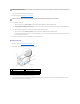
1 card 2 release lever, securing tab 3 system board connector 4 card insert 5 card-retention latch 3. If you are installing a card in an empty card connector on the system board, remove the filler bracket to create a card-slot opening at the back of the computer. Then continue with step 5. 4. If you are installing a card to replace one already installed in the computer, remove the installed card (see Removing a PCI Card). 5. Prepare the card for installation.
1 PCIe x16 card 2 release lever 3 securing slot (not all cards) 4 securing tab 5 PCIe x16 card connector 6. Place the card in the connector and press down firmly. Using the following illustration as a guide, ensure that the card is fully seated in the slot.
NOTICE: Do not route card cables over or behind the cards. Cables routed over the cards can prevent the computer cover from closing properly or cause damage to the equipment. 8. Connect any cables that should be attached to the card. 9. Perform the procedure After Working on Your Computer. NOTICE: To connect a network cable, first plug the cable into the network wall jack and then plug it into the computer. 10. If you installed a sound card: a. b. 11. ™ Technology Guide).
1 PCIe x16 card 2 release lever 3 securing slot (not all cards) 4 securing tab 5 PCIe x16 card connector 5. Grasp the card by its top corners, and ease it out of its connector. 6. If you are removing the card permanently, install a filler bracket in the empty card-slot opening. NOTE: Installing filler brackets over empty card-slot openings is necessary to maintain FCC compliance of the computer.
1 riser-card cage 4. 2 handle If you are installing a new card, remove the filler bracket to create an empty card-slot opening. If you are replacing a card that is already installed in the computer, remove the card. If necessary, disconnect any cables connected to the card. Grasp the card by its corners, and ease it out of its connector. NOTE: See the documentation that came with the card for information on configuring the card, making internal connections, or customizing it for your computer. 5.
9. Replace the riser-card cage: a. Align the tabs in the side of the riser-card cage with the slots on the side of the computer, and slide the riser-card cage down into place. b. Ensure that the riser cards are fully seated in the connectors on the system board. 1 riser-card cage 2 slots 3 riser cards (2) 4 system board connectors (2) 10. Reconnect any cables that you removed in step 3. 11. Connect any cables that should be attached to the card.
1 riser-card cage 2 handle 3. Press in on the tab to raise the card-retention latch. 4. If necessary, disconnect any cables connected to the card. 5. Grasp the card by its top corners, and ease it out of its connector. 6. If you are removing the card permanently, install a filler bracket in the empty card-slot opening. NOTE: Installing filler brackets over empty card-slot openings is necessary to maintain FCC compliance of the computer.
Internal Wireless Card - Installation The internal wireless card is an optional device. 1 wireless card assembly 2 wireless card cable to antenna 3 Wi-Fi external antenna connector 4 card retention clasp release 5 card retention clasp To install the card, do the following: 1. Perform the procedure Before Working on Your Computer. 2. If installed, remove the filler plug covering the opening in the back panel for the Wi-Fi external antenna connector. 3.
tabs on the connector faceplate pass through the opening, and the bent end of the connector faceplate is pointed away from the power supply. 9. Slide the connector sideways along the back panel slightly so that the retaining tabs on the connector faceplate hold the connector to the back panel. 10. Connect the Wi-Fi external antenna to the wireless card cable connector. 11. Replace the computer cover. 12. Restart your computer.
Back to Contents Page Dell™ Optiplex™ 960 Mini Tower/Desktop/Small Form Factor Service Manual Chassis Intrusion Switch Chassis Intrusion Switch CAUTION: Before working inside your computer, read the safety information that shipped with your computer. For additional safety best practices information, see the Regulatory Compliance Homepage at www.dell.com/regulatory_compliance. Removing the Chassis Intrusion Switch 1. Perform the procedure Before Working on Your Computer. 2.
4. Save your BIOS settings and exit system setup.
Back to Contents Page Dell™ Optiplex™ 960 Mini Tower/Desktop/Small Form Factor Service Manual Desktop Computer Cover Desktop Computer Cover Removing the Desktop Computer Cover CAUTION: Before you begin any of the procedures in this section, read the safety information that shipped with your computer. For additional safety best practices information, see the Regulatory Compliance Homepage at www.dell.com/regulatory_compliance.
a. Align the bottom of the cover with the hinge tabs located along the bottom edge of the computer. b. Using the hinge tabs as leverage, rotate the cover downward to close it. c. Snap the cover into place by pulling back on the cover release latch and then releasing the latch when the cover is properly seated. d. Ensure that the cover is seated correctly before moving the computer. NOTICE: To connect a network cable, first plug the cable into the network wall jack and then plug it into the computer.
Back to Contents Page Dell™ Optiplex™ 960 Mini Tower/Desktop/Small Form Factor Service Manual Processor Processor CAUTION: Before working inside your computer, read the safety information that shipped with your computer. For additional safety best practices information, see the Regulatory Compliance Homepage at www.dell.com/regulatory_compliance.
` 1 heatsink assembly 4. 2 captive screw housing (4) If previously cables were routed through the guides on the back of the heatsink assembly, reroute them through the guides. Removing the Processor 1. Perform the procedure Before Working on Your Computer. 2. Remove the heatsink assembly (see Remove and Replace the Fan and Shroud Assembly). NOTICE: Unless a different heatsink is required for the new processor, reuse the original heatsink assembly when you replace the processor. 3.
NOTICE: Ground yourself by touching an unpainted metal surface on the back of the computer. NOTICE: When replacing the processor, do not touch any of the pins inside the socket or allow any objects to fall on the pins in the socket. 1. Perform the procedure Before Working on Your Computer. 2. Unpack the new processor, being careful not to touch the underside of the processor.
Remove and Replace the Fan and Shroud Assembly The fan and shroud assembly can be removed and replaced without removing the heatsink. 1. Perform the procedure Before Working on Your Computer. 2. Disconnect the fan cable from the system board (see System Board Components). 3. Remove the four black screws that secure the fan and shroud assembly to the heatsink. 4. Lift the fan and shroud assembly out of the chassis. 1 fan and shroud assembly 2 fan shroud screws (4) 5.
Back to Contents Page Dell™ Optiplex™ 960 Mini Tower/Desktop/Small Form Factor Service Manual Drives Drives NOTE: If you are removing or adding a device that affects the hardware or RAID configuration of the system, BIOS settings may need to be changed. Refer to the Dell™ Technology Guide for more information. Your computer supports: l One 3.5-inch SATA (serial ATA) hard drive or up to two 2.5-inch SATA hard drives in the hard drive bay l One additional 3.
1 data interface cable connector 2 data interface connector Power Cable Connectors 1 power cable 2 power input connector Connecting and Disconnecting Drive Cables When removing a cable with a pull-tab, grasp the colored pull-tab and pull until the connector detaches. When connecting and disconnecting a cable without a pull tab, hold the cable by the black connector at each end. Drive Bay Inserts Your computer will come with a plastic insert with shoulder screws and a metal insert.
1 retention tab 2 drive bay insert Replacing Drive Bay Inserts If you are removing a drive, and need to replace the inserts: 1. At the front of the bezel, place the plastic insert over the drive bay opening and insert the tabs at the right edge of the insert into the slots at the right side of the drive bay opening. 2. Swing the left side of the insert into the opening until it snaps into place. 3. Perform the procedure After Working on Your Computer.
3. Disconnect the power and data cables from the back of the drive. 4. If you are not replacing the optical drive at this time, install the optical drive bay insert (see Replacing Drive Bay Inserts). NOTE: Contact Dell if you need a drive bay insert. Installing an Optical Drive 1. Unpack the drive and prepare it for installation. Check documentation provided for the drive to verify that the drive is configured for your computer. 2. 3. If you are installing a new drive: a.
Floppy Drive CAUTION: Before you begin any of the procedures in this section, read the safety information that shipped with your computer. For additional safety best practices information, see the Regulatory Compliance Homepage at www.dell.com/regulatory_compliance. CAUTION: To guard against electrical shock, always unplug your computer from the electrical outlet before removing the computer cover. NOTE: If you will be operating your computer without an optical drive or a 3.
3. Install the four shoulder screws onto the sides of the new floppy drive and tighten them. 4. Attach the power and data cables to the floppy drive. Ensure that the other end of the cable attaches to the DSKT2 connector on the system board (see System Board Components). 5. Align the shoulder screws with the screw guides, and slide the drive into the bay until it clicks into place. 1 power cable 2 slot verification number 6.
Removing a Media Card Reader 1. Perform the procedure Before Working on Your Computer. NOTE: Since the following steps do not require the complete removal of the optical drive, it is not necessary to disconnect the cables connecting the optical drive. 2. Remove the optical drive (if one exists) and carefully set it aside (see Removing an Optical Drive). NOTICE: Do not pull the drive out of the computer by the drive cables. Doing so may cause damage to cables and the cable connectors. 3.
3. Insert the four shoulder screws into the sides of the new media card reader and tighten them. 4. Align the shoulder screws with the screw guides in the mounting rack, and slide the media card reader into the bay until it clicks into place. 1 media card reader 5. 1 2 slot verification number Attach the power and data cable to the media card reader and system board connector. power.and data cable 6. Replace the optical drive (see Optical Drive). 7.
CAUTION: Before you begin any of the procedures in this section, read the safety information that shipped with your computer. For additional safety best practices information, see the Regulatory Compliance Homepage at www.dell.com/regulatory_compliance. NOTICE: To guard against electrical shock, always unplug your computer from the electrical outlet before removing the computer cover. NOTICE: When handling 2.5-inch hard drives, avoid pressing on the drive label. This can cause serious damage to the drive.
3 drive bay caddy 8. If the primary hard drive is a 2.5-inch hard drive, it is mounted on the top (flat side) of a 2.5-inch hard drive caddy in the drive bay caddy. To remove the primary drive: a. Remove the 2.5-inch hard drive caddy from the drive bay caddy by gently bending out the release tabs on the side of the caddy and lifting out the 2.5-inch hard drive caddy. 1 2.5-inch hard drive and 2.5-inch hard drive caddy 2 release tabs (2) 3 drive bay caddy b.
3. If installing 2.5-inch hard drives as the primary hard drive: a. Position the new 2.5-inch hard drive into the flat side of the 2.5-inch hard drive caddy with the side of the drive with the label plate facing away from the caddy, and the connector end of the drive toward the end of the caddy with the cable cutout (back end). 1 2.5-inch hard drive caddy, flat side up 2 2.5-inch hard drive, connector end 3 cable cutout 4 screws (4) 1 b.
1 3.5-inch hard drive or 2.5-inch hard drive with caddy 2 slot verification number 6. Route the hard drive power and data cables through cable channels and attach them to cable bundles as needed. 7. Replace the floppy drive or media card reader, if it was installed (see Installing a Floppy Drive, or Installing a Media Card Reader). 8. Replace the optical drive, if it was installed (see Installing an Optical Drive). 9.
3. Remove the optical drive, if installed (see Removing an Optical Drive). 4. If the secondary drive is a 3.5-inch hard drive: a. Lift the drive-release latch and slide the drive toward the front of the computer. Then, lift it out of the chassis. NOTICE: Do not pull the drive out of the computer by the drive cables. Doing so may cause damage to cables and the cable connectors. 1 drive-release latch 5. 2 hard drive If the secondary hard drive is a 2.
1 2.5-inch hard drive and 2.5-inch hard drive caddy 2 release tabs (2) 3 drive bay caddy e. f. 6. 1 The secondary 2.5-inch hard drive is mounted on the U-shaped side of the 2.5-inch hard drive caddy. Disconnect the power cable y-adapter from the secondary hard drive. Remove the secondary drive from the caddy by removing the four retaining screws, two on each side of the drive. Perform the procedure After Working on Your Computer. secondary 2.5" hard drive 2 2.
5. d. Connect the SATA data cable to the hard drive and to the SATA1 connector on the system board (see System Board Components). e. Lower the hard drive into the floppy drive/media card reader bay. Slide the drive toward the back of the chassis until it locks into place. If installing 2.5-inch hard drives as the secondary hard drive: a. Press in on the two securing clips on each side of the drive bay caddy and slide the caddy towards the back of the computer.
1 2.5-inch hard drive caddy, U-shaped side up 2 2.5-inch hard drive, connector end 3 cable cutout 4 screws (4) e. f. 1 Secure the drive to the drive caddy with four screws, two on each side. Attach the power cable y-adapter to the hard drives installed in the caddy. power cable adapter g. Install the 2.5-inch hard drive caddy into the drive bay caddy by gently bending out the release tabs on the side of the caddy and positioning the 2.5-inch drive caddy in the drive bay caddy.
1 2.5-inch hard drive caddy in drive bay caddy j. 2 slot verification number Replace the floppy drive or media card reader, if it was installed (see Installing a Floppy Drive, or Installing a Media Card Reader). 6. Route the hard drive power and data cables through cable channels and attach them to the cable bundle as needed. 7. Replace the optical drive, if it was installed (see Installing an Optical Drive). 8.
Back to Contents Page Dell™ Optiplex™ 960 Mini Tower/Desktop/Small Form Factor Service Manual I/O Assembly I/O Assembly Removing the I/O Assembly CAUTION: Before working inside your computer, read the safety information that shipped with your computer. For additional safety best practices information, see the Regulatory Compliance Homepage at www.dell.com/regulatory_compliance. CAUTION: To guard against electrical shock, always unplug your computer from the electrical outlet before removing the cover.
1 I/O assembly 3 I/O assembly cables/connectors 2 securing tab Replacing the I/O Assembly To replace the I/O assembly, do the following: 1. Perform the procedure Before Working on Your Computer. NOTE: Use the guides on the I/O assembly bracket to help position the I/O assembly in place, and use the notch on the I/O assembly bracket to help seat the panel. 2. 1 Remove the bezel: a. Lift the three retention tabs to release the top edge of the bezel. b.
1 I/O assembly 3 securing tab 2 I/O assembly cables, connectors (2) 4. Push the I/O connector block into the I/O assembly opening until it snaps into place. 5. Plug the I/O assembly cable connectors into their system board connectors (see System Board Components). 6. Join the I/O assembly cables to the cable bundle routed through the middle of the chassis. 7. Replace the bezel. 8. Perform the procedure After Working on Your Computer). 9.
Back to Contents Page Dell™ Optiplex™ 960 Mini Tower/Desktop/Small Form Factor Service Manual Power Supply Power Supply Replacing the Power Supply CAUTION: Before working inside your computer, read the safety information that shipped with your computer. For additional safety best practices information, see the Regulatory Compliance Homepage at www.dell.com/regulatory_compliance.
11. Replace the optical drive (see Optical Drive). 12. Connect the AC power cable to the connector. 13. Perform the procedure After Working on Your Computer. DC Power Connectors DC Power Connector P1 Pin Number Signal name 18-AWG Wire 1 +3.3 VDC Orange 2 +3.3 VDC Orange 3 GND Black 4 +5 VDC Red 5 GND Black 6 +5 VDC Red 7 GND Black 8 PS_PWRGOOD* Gray 9 P5AUX Purple 10 +12 VDC White 11 +12 VDC White 12 +3.3 VDC Orange 13 +3.
23 +5 VDC Red 24 GND Black *Use 22-AWG wire instead of 18-AWG wire. DC Power Connector P2 Pin Number Signal Name 18-AWG Wire 1 GND Black 2 GND Black 3 +12 VDC Yellow 4 +12 VDC Yellow DC Power Connector P4 Pin Number Signal Name 22-AWG Wire 1 +5 VDC Red 2 GND Black 3 GND Black 4 +12 VDC Yellow DC Power Connector P5 and P6 Pin Number Signal name 18-AWG Wire 1 +3.
Back to Contents Page Dell™ Optiplex™ 960 Mini Tower/Desktop/Small Form Factor Service Manual Internal Speaker Internal Speaker Installing an Internal Speaker The internal speaker is an optional device. CAUTION: Before working inside your computer, read the safety information that shipped with your computer. For additional safety best practices information, see the Regulatory Compliance Homepage at www.dell.com/regulatory_compliance.
1. Perform the procedure Before Working on Your Computer. 2. Disconnect the speaker cable from the system board. 3. To remove the internal speaker, press the locking tab, shift the speaker to move the speaker housing retention tabs out of the grill retention tabs, and lift the speaker from the chassis. 4. Perform the procedure After Working on Your Computer.
Back to Contents Page Dell™ Optiplex™ 960 Mini Tower/Desktop/Small Form Factor Service Manual System Board Components System Board Components 1 fan connector (FAN_CPU) 2 processor connector (CPU) 3 processor power connector (12VPOWER) 4 memory module connectors (DIMM_1, DIMM_2, DIMM_3, DIMM_4) 5 SATA drive connectors (3) 6 password jumper (PSWD) 7 internal USB connector (FLEX_USB) 8 Service Mode jumper (SERVICE_MODE) 9 power connector (POWER) 10 system status LEDs panel connector (FRONT
Back to Contents Page Memory Dell™ Optiplex™ 960 Mini Tower/Desktop/Small Form Factor Service Manual You can increase your computer memory by installing memory modules on the system board. Your computer supports DDR2 memory. For additional information on the type of memory supported by your computer, see the appropriate specifications for your system in this book. DDR2 Memory Overview l When installed in pairs, DDR2 memory modules should be of matched memory size and speed.
If you are using a 32-bit operating system such as Microsoft® Windows® Vista®, your computer will support a maximum of 4 GB of memory. If you are using a 64-bit operating system, your computer will support a maximum of 8 GB (2-GB DIMMs in each of the four slots) of memory. Installing Memory CAUTION: Before you begin any of the procedures in this section, read the safety information that shipped with your computer.
6. Connect your computer and devices to electrical outlets, and turn them on. 7. When the message appears stating that memory size has changed, press to continue. 8. Log on to your computer. 9. Right-click the My Computer icon on your Windows desktop and click Properties. 10. Click the General tab. 11. To verify that the memory is installed correctly, check the amount of memory (RAM) listed.
Dell™ OptiPlex™ 960 Service Manual Mini Tower Computer Working on Your Computer Inside View of Your Computer System Board Components Cover Chassis Intrusion Switch Cards Drives Processor I/O Panel Power Supply Speakers Battery System Board Memory Troubleshooting Tips Contacting Dell Notes, Notices, and Cautions NOTE: A NOTE indicates important information that helps you make better use of your computer.
Back to Contents Page Dell™ Optiplex™ 960 Mini Tower/Desktop/Small Form Factor Service Manual Cards Cards CAUTION: Before working inside your computer, read the safety information that shipped with your computer. For additional safety best practices information, see the Regulatory Compliance Homepage at www.dell.com/regulatory_compliance.
1 card retention latch 2 alignment guide 3 card 4 release lever, securing tab 5 card connector 6 release tab 3. If you are installing a new card, remove the filler bracket to create a card- slot opening. Then continue with step 5. 4. If you are replacing a card that is already installed in the computer, remove the card. If necessary, disconnect any cables connected to the card. 5.
10. Connect any cables that should be attached to the card. See the documentation for the card for information about the card's cable connections. 11. Reseat the card retention latch. 12. Perform the procedure After Working on Your Computer. 13. If you installed a sound card: 14. a. Enter system setup, select Audio Controller, and change the setting to Off (see the Dell™ Technology Guide for more information on system setup). b. Connect external audio devices to the sound card's connectors.
7. 8. If you removed a sound card: a. Enter system setup, select Audio Controller, and change the setting to On. (See the Dell™ Technology Guide for more information). b. Connect external audio devices to the audio connectors on the back panel of the computer. If you removed a network-adapter card connector: a. Enter system setup, select Network Controller, and change the setting to On. (See the Dell™ Technology Guide for more information). b.
NOTICE: When routing the wireless card cable through the chassis, avoid making sharp bends. This can cause signal degradation. 6. Route the wireless card cable through the cable guides on the top of the heatsink assembly, along the cable bundle for the front panel wiring, and through the cable clip on the side of the power supply. 7. Remove the plug on the back panel where the external connector for the Wi-FI antenna is installed. 8.
Back to Contents Page Dell™ Optiplex™ 960 Mini Tower/Desktop/Small Form Factor Service Manual Chassis Intrusion Switch Chassis Intrusion Switch CAUTION: Before working inside your computer, read the safety information that shipped with your computer. For additional safety best practices information, see the Regulatory Compliance Homepage at www.dell.com/regulatory_compliance. Removing the Chassis Intrusion Switch 1. Perform the procedure Before Working on Your Computer. 2.
4. Save your BIOS settings and exit system setup.
Back to Contents Page Dell™ Optiplex™ 960 Mini Tower/Desktop/Small Form Factor Service Manual Mini Tower Computer Cover Mini Tower Computer Cover Removing the Mini Tower Computer Cover CAUTION: Before working inside your computer, read the safety information that shipped with your computer. For additional safety best practices information, see the Regulatory Compliance Homepage at www.dell.com/regulatory_compliance.
Gently pull the power cables toward you so that they do not get caught underneath the drives. 2. Ensure that no tools or extra parts are left inside the computer. 3. To replace the cover: a. Align the bottom of the cover with the hinge tabs located along the bottom edge of the computer. b. Using the hinge tabs as leverage, rotate the cover downward to close it. c. Snap the cover into place by pulling back on the cover release latch and then releasing the latch when the cover is properly seated. d.
Back to Contents Page Dell™ Optiplex™ 960 Mini Tower/Desktop/Small Form Factor Service Manual Processor Processor CAUTION: Before working inside your computer, read the safety information that shipped with your computer. For additional safety best practices information, see the Regulatory Compliance Homepage at www.dell.com/regulatory_compliance.
1 heatsink assembly 3 captive screw (2) 4. 2 heat-sink assembly bracket Reroute cables removed earlier through the cable guides on the heatsink assembly. Reconnect them as needed. Removing the Processor 1. Perform the procedure Before Working on Your Computer. 2. Remove the heatsink assembly (see Removing the Heatsink Assembly). NOTICE: Unless a different heatsink is required for the new processor, reuse the original heatsink assembly when you replace the processor. 3.
Installing the Processor NOTICE: Ground yourself by touching an unpainted metal surface on the back of the computer. NOTICE: When replacing the processor, do not touch any of the pins inside the socket or allow any objects to fall on the pins in the socket. 1. FPerform the procedure Before Working on Your Computer. 2. Unpack the new processor, being careful not to touch the underside of the processor.
3. Disconnect the fan cable from the system board (see System Board Components). 4. Lift (press up) the fan retention tab on the lower side of the fan assembly (toward the bottom of the computer) while pulling back (away from the chassis) the tab on the upper side of the fan assembly, and simultaneously sliding the assembly toward the back of the chassis to release it from the chassis.
Back to Contents Page Dell™ Optiplex™ 960 Mini Tower/Desktop/Small Form Factor Service Manual Drives Drives NOTE: If you are removing or adding a device that affects the hardware or RAID configuration of the system, BIOS settings may need to be changed. Refer to the Dell™ Technology Guide for more information. Your computer supports: l Up to Two 3.5-inch or up two 2.5-inch SATA (Serial ATA) hard drives l One 3.5-inch floppy drive or media card reader l Two 5.
1 data interface cable connector 2 data interface connector Power Cable Connectors 1 power cable 2 power input connector Connecting and Disconnecting Drive Cables When removing a cable with a pull-tab, grasp the colored pull-tab and pull until the connector detaches. When connecting and disconnecting a cable without a pull tab, hold the cable by the black connector at each end. Hard Drive The OptiPlex 960 mini-tower chassis support either one or two 3.5-inch hard drives, or one or two 2.
The drive to be removed may be a 3.5-inch hard drive installed in the upper drive bay or lower drive bay, or 2.5-inch hard drive in the upper bay, and may be a primary drive or secondary drive. The upper drive bay always contains the primary hard drive, and, if a drive is installed in the lower drive bay, it is always configured as a secondary hard drive. When two 2.5-inch hard drives are installed in the system (as primary and secondary drives), both are mounted on the same 2.
1 hard drive or 2.5-inch hard drive caddy 7. 2 drive bay caddy If the drive being removed is a 2.5-inch hard drive: a. 1 Remove the 2.5-inch hard drive caddy from the drive bay caddy by gently bending out the sides of the drive bay caddy lifting out the hard drive caddy. hard drive or 2.5-inch hard drive caddy b. drive bay caddy Detach the hard drive to be removed from the 2.5-inch hard drive caddy by removing the four screws, two on each side, that secure it to the caddy.
f. On the Settings menu, select Drives, and select Drives on the sub-menu. g. Disable the SATA port for the secondary hard drive (normally SATA1). h. Click Apply, then Exit. i. If the new primary hard drive is a bootable drive, skip the rest of this step. j. Insert a bootable medium into a boot drive. k. Reboot your computer and press F12 when prompted to enter the Boot Device Menu. l. m. Select the drive with the bootable media and press Next.
1 2.5-inch hard drive caddy (flat side up) 2 2.5-inch hard drive (primary drive shown) 3 end of caddy with cable cutout 4 screws (4) 1 2.5-inch hard drive caddy (Ushaped side up) 2 2.5-inch hard drive (secondary drive shown) 3 end of caddy with cable cutout 4 screws (4) 1 b. Secure the drive to the drive caddy with four screws, two on each side. c. Connect a power cable y-adapter to the hard drive(s) installed in the caddy. power cable adapter d. Install the 2.
1 2.5-inch hard drive and caddy (shown with primary 2 cable cutouts drive) 3 drive bay caddy 4 pins (2 on each side) 7. Carefully slide the drive bay caddy into the drive bay until it snaps into place. If the drive bay caddy contains the primary hard drive, insert the caddy into the upper-most bay. 8. Connect the power and data cables to the drive(s). NOTICE: Always connect the primary hard drive data cable to the SATA0 connector on the system board.
Refer to documentation for your operating system for instructions. ™ 15. Test the hard drive by running the Dell Diagnostics (see the Dell Technology Guide). 16. If the drive you just installed is the primary drive, install a bootable operating system onto the drive, if necessary. Remove the Drive Bezel To remove the drive bezel: 1. Slide the drive release latch toward the bottom of the computer to release the bezel. 2. Rotate the bezel away from the right side of the chassis. 3.
CAUTION: Before working inside your computer, read the safety information that shipped with your computer. For additional safety best practices information, see the Regulatory Compliance Homepage at www.dell.com/regulatory_compliance. CAUTION: To guard against electrical shock, always unplug your computer from the electrical outlet before removing the computer cover. Removing the Floppy Drive 1. If the floppy drive you are removing will not be replaced: a.
4. Align the shoulder screws on the floppy drive with the shoulder screw slots, and gently slide it into the bay until it clicks into place. 1 floppy drive 3 shoulder screw slots (2) 2 shoulder screws (4) 5. Replace the drive bezel (see Remove the Drive Bezel). 6. Attach the data cables to the floppy drive and to the system board. Route the data cable through the cable guides on the fan shroud. Attach the power cable to the drive.
Media Card Reader CAUTION: Before working inside your computer, read the safety information that shipped with your computer. For additional safety best practices information, see the Regulatory Compliance Homepage at www.dell.com/regulatory_compliance. CAUTION: To guard against electrical shock, always unplug your computer from the electrical outlet before removing the computer cover. Removing the Media Card Reader 1. Perform the procedure Before Working on Your Computer. 2.
4. Align the shoulder screws on the media card reader with the shoulder screw slots, and gently slide it into the bay until it clicks into place. 1 media card reader 3 shoulder screw slots (2) 2 shoulder screws (4) 5. Replace the drive bezel (see Replace the Drive Bezel). 6. Attach the power and data cable to the media card reader and to internal USB connector on the system board (see System Board Components). 1 data/power cable 2 media card reader 7.
Removing an Optical Drive 1. Perform the procedure Before Working on Your Computer. 2. Disconnect the power and data cables from the back of the drive. 3. Remove the drive bezel (see Remove the Drive Bezel). 4. Slide the drive release latch toward the base of the computer and remove the optical drive from the computer. 1 optical drive 5. 2 drive release latch If you are not installing another device into the optical drive bay, do the following: a.
1 optical drive 3 shoulder screw slots (2) 2 shoulder screws (3) 6. Replace the drive bezel (see Remove the Drive Bezel). 7. Connect the power and data cables to the drive and to the system board. Always connect the optical drive SATA cable to a system board SATA connector that is labeled with a number higher than those connected to any hard drives installed in the computer. 1 power cable 3 SATA optical drive connector 2 data cable 8.
Back to Contents Page Dell™ Optiplex™ 960 Mini Tower/Desktop/Small Form Factor Service Manual I/O Assembly I/O Assembly Removing the I/O Assembly CAUTION: Before working inside your computer, read the safety information that shipped with your computer. For additional safety best practices information, see the Regulatory Compliance Homepage at www.dell.com/regulatory_compliance. CAUTION: To guard against electrical shock, always unplug your computer from the electrical outlet before removing the cover.
1 I/O assembly 3 I/O assembly cable connectors 2 securing screw Replacing the I/O Assembly 1. Perform the procedure Before Working on Your Computer. 2. Remove the drive bezel, if installed (see Remove the Drive Bezel). 3. Remove the bezel, if installed (see Remove the Bezel). 4. Feed the I/O assembly cables into the front of the chassis through the opening for the I/O assembly until the assembly is in place.
10. Replace the optical drive, if removed earlier (see Replacing or Installing an Optical Drive). 11. Replace the drive bay caddy. 12. Replace the drive bezel (see Replace the Drive Bezel). 13. Perform the procedure After Working on Your Computer. 14. Reboot your computer and exercise the I/O panel to ensure that it is working properly. Remove the Bezel 1 1. Perform the procedure Before Working on Your Computer. 2. Release the seven securing tabs located behind the bezel 3.
Back to Contents Page Dell™ Optiplex™ 960 Mini Tower/Desktop/Small Form Factor Service Manual Power Supply Power Supply Replacing the Power Supply CAUTION: Before working inside your computer, read the safety information that shipped with your computer. For additional safety best practices information, see the Regulatory Compliance Homepage at www.dell.com/regulatory_compliance.
DC Power Connectors DC Power Connector P1 Pin Number Signal name 18-AWG Wire 1 +3.3 VDC Orange 2 +3.3 VDC Orange 3 GND Black 4 +5 VDC Red 5 GND Black 6 +5 VDC Red 7 GND Black 8 PS_PWRGOOD Gray 9 P5AUX Purple 10 V_12P0_DIG White 11 V_12P0_DIG White 12 +3.3 VDC Orange 13 +3.
DC Power Connector P2 Pin Number Signal Name 18-AWG Wire 1 GND Black 2 GND Black 3 +12 VADC Yellow 4 +12 VADC Yellow DC Power Connectors P3, P5, P8, and P9 Pin Number Signal name 18-AWG Wire 1 +3.
Back to Contents Page Dell™ Optiplex™ 960 Mini Tower/Desktop/Small Form Factor Service Manual Internal Speaker Internal Speaker Installing an Internal Speaker The internal speaker is an optional device. CAUTION: Before working inside your computer, read the safety information that shipped with your computer. For additional safety best practices information, see the Regulatory Compliance Homepage at www.dell.com/regulatory_compliance.
1. Perform the procedure Before Working on Your Computer. 2. Disconnect the cable from the INT SPKR1 connector on the system board (see System Board Components). 3. To remove the internal speaker, press the locking tab, shift the speaker to move the speaker housing retention tabs out of the retention tabs on the grill, and lift the speaker from the chassis. 4. Perform the procedure After Working on Your Computer.
Back to Contents Page Dell™ Optiplex™ 960 Mini Tower/Desktop/Small Form Factor Service Manual System Board Components System Board Components 1 connector for optional wireless card (PCIE_WLS1) 3 connector for optional internal speaker (INT_SPKR1) 4 2 thermal sensor connector (THRML1) fan connector (FAN_CPU1) 5 processor connector (CPU) 6 processor power connector (12VPOWER) 7 auxiliary power LED (AUX_POWER) 8 memory module connectors (4) 9 password reset pins (PSWD) 10 system status LEDs
Back to Contents Page Dell™ Optiplex™ 960 Mini Tower/Desktop/Small Form Factor Service Manual Cards Cards CAUTION: Before you begin any of the procedures in this section, read the safety information that shipped with your computer. For additional safety best practices information, see the Regulatory Compliance Homepage at www.dell.com/regulatory_compliance.
1 card retention latch 2 release tab 3 card 4 card-edge connector 5 card connector 3. If you are installing a new card, remove the filler bracket to create a card- slot opening. Then continue with step 5. 4. If you are replacing a card that is already installed in the computer, remove the card. If necessary, disconnect any cables connected to the card. Then continue with step 5. 5. Prepare the card for installation.
b. Connect the network cable to the network adapter card's connectors. Do not connect the network cable to the integrated network connector on the back panel of the computer. NOTICE: If you disable the integrated network adapter, you will not have AMT functionality. 13. Install any drivers required for the card as described in the card documentation. Removing a PCI Card 1. Perform the procedure Before Working on Your Computer. NOTE: For PCI card locations, see System Board Components. 2.
NOTICE: To connect a network cable, first plug the cable into the network wall jack and then plug it into the computer. NOTE: See the documentation for the card for information about the card's cable connections. 11. If you removed a network-adapter card connector: a. Enter system setup, select Integrated NIC from the Onboard Devices group, and change the setting to On (see the Dell b. Connect the network cable to the integrated network connector on the back panel of the computer.
1 card fully seated 2 card not fully seated 3 bracket within slot 4 bracket caught outside of slot NOTICE: Do not route card cables over the cards. Cables routed over the cards can prevent the computer cover from closing properly or cause damage to the equipment. 7. Connect any cables that should be attached to the card. 8. Before you close the card retention mechanism, ensure that: 9. 10. l The tops of all cards and filler brackets are flush with the alignment bar.
1 PCIe x16 card/PCIe x16 DVI-card 2 release lever 3 securing slot (not all cards) 4 securing tab 5 PCIe x16 card connector 5. If you are removing the card permanently, install a filler bracket in the empty card-slot opening. NOTE: Installing filler brackets over empty card-slot openings is necessary to maintain FCC compliance of the computer. The brackets keep dust and dirt out of your computer and maintain the airflow that cools your computer. 6. 7.
1 wireless card assembly 2 wireless card cable to antenna 3 Wi-Fi external antenna connector 4 card retention clasp release 5 card retention clasp To install the card, do the following: 1. Perform the procedure Before Working on Your Computer. 2. If installed, remove the filler plug covering the opening in the back panel for the Wi-Fi external antenna connector. 3. Locate the wireless card connector on the system board (see System Board Components). 4.
11. Replace the computer cover. 12. Restart your computer. Setup the wireless device software as needed to support your wireless network. Internal Wireless Card - Removal To remove an internal wireless card do the following: 1. Perform the procedure Before Working on Your Computer. 2. Disconnect the Wi-Fi external antenna from the connector on the back of the computer. 3.
Back to Contents Page Dell™ Optiplex™ 960 Mini Tower/Desktop/Small Form Factor Service Manual Chassis Intrusion Switch Chassis Intrusion Switch CAUTION: Before working inside your computer, read the safety information that shipped with your computer. For additional safety best practices information, see the Regulatory Compliance Homepage at www.dell.com/regulatory_compliance. Removing the Chassis Intrusion Switch 1. Perform the procedure Before Working on Your Computer. 2.
the setting, move to the Apply button and press Enter. NOTE: The default setting is On-Silent. 4. Save your BIOS settings and exit system setup.
Back to Contents Page Dell™ Optiplex™ 960 Mini Tower/Desktop/Small Form Factor Service Manual Small Form Factor Computer Cover Small Form Factor Computer Cover Removing the Small Form Factor Computer Cover CAUTION: Before you begin any of the procedures in this section, read the safety information that shipped with your computer. For additional safety best practices information, see the Regulatory Compliance Homepage at www.dell.com/regulatory_compliance.
a. Align the bottom of the cover with the hinge tabs located along the bottom edge of the computer. b. Using the hinge tabs as leverage, rotate the cover downward to close it. c. Snap the cover into place by pulling back on the cover release latch and then releasing the latch when the cover is properly seated. d. Ensure that the cover is seated correctly before moving the computer. NOTICE: To connect a network cable, first plug the cable into the network wall jack and then plug it into the computer.
Back to Contents Page Dell™ Optiplex™ 960 Mini Tower/Desktop/Small Form Factor Service Manual Processor Processor CAUTION: Before working inside your computer, read the safety information that shipped with your computer. For additional safety best practices information, see the Regulatory Compliance Homepage at www.dell.com/regulatory_compliance.
1 center cover latch 2 processor cover 3 processor 4 socket 5 release lever NOTICE: When replacing the processor, do not touch any of the pins inside the socket or allow any objects to fall on the pins in the socket. 9. Gently remove the processor from the socket. Leave the release lever extended in the release position so that the socket is ready for the new processor. Installing the Processor NOTICE: Ground yourself by touching an unpainted metal surface on the back of the computer.
1 processor cover 2 tab 3 processor 4 processor socket 5 center cover latch 6 release lever 7 front alignment-notch 8 socket and processor pin-1 indicator 9 rear alignment-notch NOTICE: To avoid damage, ensure that the processor aligns properly with the socket, and do not use excessive force when you install the processor. 6. Set the processor lightly in the socket and ensure that the processor is positioned correctly. 7.
1 heatsink assembly 3 fan cable connectors (2) 2 captive screw in housing (4) 12. If the system contained a wireless card that was removed in a previous step, replace the card (see Internal Wireless Card - Installation). 13. Reroute cables through guides on the fan shroud. 14. Replace the optical drive (see Replacing or Installing an Optical Drive). 15. Replace the hard drive and shroud assembly (see Replacing the Hard Drive and Shroud Assembly). 16.
1 fan and shroud assembly 3 fan cable connectors (2) 9. 2 fan shroud screws (4) Position the new fan and shroud assembly onto the heatsink, aligning the screw holes in the shroud with the holes in the heatsink. 10. Secure the fan shroud to the heatsink with the four screws removed in the step above. 11. Connect the two fan cables to the system board (see System Board Components). 12.
Back to Contents Page Dell™ Optiplex™ 960 Mini Tower/Desktop/Small Form Factor Service Manual `Drives `Drives NOTE: If you are removing or adding a device that affects the hardware or RAID configuration of the system, BIOS settings may need to be changed. Refer to the Dell™ Technology Guide for more information. Your computer supports: l One 3.5-inch SATA (serial ATA) hard drive or two 2.
1 data interface cable connector 2 SATA interface connector Power Cable Connectors 1 power cable 2 power input connector Connecting and Disconnecting Drive Cables When removing an cable with a pull-tab, grasp the colored pull-tab and pull until the connector detaches. When connecting and disconnecting a SATA data cable, hold the cable by the black connector at each end. Removing Drive Bay Inserts If you are installing a new drive: 1 1. Perform the procedure Before Working on Your Computer. 2.
Replacing Drive Bay Inserts If you are removing a drive, and need to replace the inserts: 1. From inside the chassis, place the plastic insert over the drive bay opening and insert the tabs at the right edge of the insert into the slots at the right side of the drive bay opening. 2. Swing the left side of the insert into the opening until it snaps into place. Hard Drive The computer may include one 3.5-inch hard drive, or one or two 2.5-inch hard drives.
1 power cable 2 SATA data cable Removing the Hard Drive 1. If you are removing a hard drive that contains data you want to keep, back up your files before you begin this procedure. 2. Perform the procedure Before Working on Your Computer. 3. Lay the computer on its side so that the system board is on the bottom of the inside of the computer. 4. Remove the hard drive and shroud assembly (see Removing the Hard Drive and Shroud Assembly). 5. If you are removing a 3.5-inch drive: a.
1 2.5-inch hard drive mounted as the primary drive 1 2.5-inch hard drive mounted as the secondary drive 2 2.5-inch hard drive caddy 2 2.5-inch hard drive caddy c. If the primary 2.5-inch hard drive was removed, and will be replaced by the secondary hard drive installed on the caddy, remove the secondary drive and install it on the mount it on the flat side of the 2.5-inch hard drive caddy. d. If the primary 2.
1 2.5" hard drive with caddy 2 hard drive shroud 3 pins (2 on each side) 4 release tabs (2) b. 3. Install the hard drive and shroud assembly in the chassis (see Replacing the Hard Drive and Shroud Assembly). If you are installing a 2.5-inch drive: a. Remove the hard drive and shroud assembly, if necessary (see Removing the Hard Drive and Shroud Assembly). b. Remove the 2.5-inch hard drive caddy from the shroud by slightly pulling out the release tabs to free the caddy. 1 2.
1 d. Secure the drive to the drive caddy with four screws, two on each side. e. Attach the power cable Y-adapter to the hard drive(s) mounted on the caddy. power cable Y-adapter f. g. Install the drive caddy in the drive shroud by slightly pulling out the release tabs on the drive shroud and aligning the pins inside the shroud with the holes on the sides of the drive caddy. The flat side of the caddy must be oriented toward the system board when the hard drive and shroud assembly is installed.
1 power cable 2 SATA data cable 4. Check all connectors to ensure that they are properly cabled and firmly seated. 5. Gently insert the hard drive and shroud assembly tabs into the alignment slots on the back of the chassis and rotate the assembly downward until it clicks into place. 1 release tabs (2) 2 hard drive and shroud assembly 3 shroud alignment tabs and slots (3) 6. Route the SATA data cable(s) and cables removed earlier through the cable channel on the side of the hard drive shroud.
1 drive release latch 5. 6. 2 optical drive If the optical drive is not being replaced after removal: a. Remove the hard drive and shroud assembly (see Removing the Hard Drive and Shroud Assembly). a. Disconnect the SATA cable from the system board and remove the cable from the chassis. b. Replace the hard drive and shroud assembly. Perform the procedure After Working on Your Computer. Installing an Optical Drive 1. Unpack the drive and prepare it for installation.
6. Check all cable connections. 7. Replace the hard drive and shroud assembly (see Replacing the Hard Drive and Shroud Assembly). 8. Check cable routing. Route cables through cable guides to provide airflow for the fan and cooling vents. 9. Perform the procedure After Working on Your Computer. 10. See the documentation that came with the drive for instructions on installing any software required for drive operation. 11. Enter system setup and select the appropriate Drive option (see the Dell 12.
1 drive release tab 2 floppy drive 6. Push down the drive release latch and slide the floppy drive towards the back of the computer. Then lift it out of the chassis. 7. If the drive is not being replaced with any device: a. Disconnect the drive data cable from the connector on the system board, and remove it from the chassis. b. Remove the bezel (see Remove the Bezel). c. Install an insert, if available, into the bezel to cover the drive bay. d.
1 floppy drive 3 bracket slots (3) 4. 2 screws (3) Insert the data cable into the connector on the system board (see System Board Components). Route the data cable under the guides on the sides of the fan shroud. 1 cable release tab 3 cable routing guide 2 floppy drive data cable edge connector 5. Insert the floppy drive cable into the cable release tab on the floppy drive and press down on the tab until it clicks to lock it in place. 6.
CAUTION: Before you begin any of the procedures in this section, read the safety information that shipped with your computer. For additional safety best practices information, see the Regulatory Compliance Homepage at www.dell.com/regulatory_compliance. CAUTION: To guard against electrical shock, always unplug your computer from the electrical outlet before removing the computer cover. Removing a Media Card Reader 1. FPerform the procedure Before Working on Your Computer. 2.
e. f. 3. Remove the three shoulder screws from the inside of the drive bay insert, and install them onto the media card reader. Remove the hard drive and shroud assembly (see Removing the Hard Drive and Shroud Assembly). Align the screws on the media card reader with the bracket slots in the computer, and gently move the drive forward until it clicks into place. 1 media card reader 3 bracket rails (3) 4.
11. Verify that your computer works correctly by running the Dell Diagnostics (see the Dell ™ Technology Guide). Remove the Bezel Lift the three front cover retention tabs to release the top edge of the cover. Roll the cover down and lift it away from the chassis. 1 bezel 2 retention tabs (3) Replacing the Bezel To replace the bezel, insert the hooks at the bottom of the bezel into the slots provided at the base of the chassis, and rotate the bezel toward the chassis until it snaps into place.
Back to Contents Page Dell™ Optiplex™ 960 Mini Tower/Desktop/Small Form Factor Service Manual I/O Assembly I/O Assembly Removing the I/O Assembly CAUTION: Before working inside your computer, read the safety information that shipped with your computer. For additional safety best practices information, see the Regulatory Compliance Homepage at www.dell.com/regulatory_compliance.
To replace the I/O assembly, do the following: 1. Remove the computer cover, if installed (see System Board Components). NOTE: Use the guides on the I/O assembly bracket to help position the I/O assembly in place, and use the notch on the I/O assembly bracket to help seat the panel. 2. Remove the bezel (see Remove the Bezel). 3. Feed the I/O assembly cables into the front of the chassis through the opening for the I/O assembly until the assembly is in place.
Back to Contents Page Dell™ Optiplex™ 960 Mini Tower/Desktop/Small Form Factor Service Manual Power Supply Power Supply Replacing the Power Supply CAUTION: Before working inside your computer, read the safety information that shipped with your computer. For additional safety best practices information, see the Regulatory Compliance Homepage at www.dell.com/regulatory_compliance.
14. Reconnect the DC power cables to the system board and drives (see System Board Components and `Drives). 15. Replace the floppy drive or media card reader (see Installing a Floppy Drive). 16. Replace the optical drive (see Installing an Optical Drive). 17. Replace the hard drive and shroud assembly (see Replacing the Hard Drive and Shroud Assembly). 18. Perform the procedure After Working on Your Computer. 19. Connect the AC power cable to the power supply AC power connector.
12 +3.3 V Orange 13 (optional) +3.3V Orange 14 -12 V* Blue 15 GND Black 16 PWR_PS_ON Green 17 GND Black 18 GND Black 19 GND Black 20 NC NC 21 VCC (+5V) Red 22 VCC (+5V) Red 23 VCC (+5V) Red 24 GND Black *Use 22-AWG wire instead of 18-AWG wire. DC Power Connector P2 Pin Number Signal Name 18-AWG Wire 1 GND Black 2 GND Black 3 +12 VDC Yellow 4 +12 VDC Yellow DC Power Connector P3 Pin Number Signal name 18-AWG Wire 1 +3.
2, 3 +5VDC Red 4 N/A N/A 5, 6 COM Black Back to Contents Page
Back to Contents Page Dell™ Optiplex™ 960 Mini Tower/Desktop/Small Form Factor Service Manual Internal Speaker Internal Speaker Installing an Internal Speaker The internal speaker is an optional device. CAUTION: Before working inside your computer, read the safety information that shipped with your computer. For additional safety best practices information, see the Regulatory Compliance Homepage at www.dell.com/regulatory_compliance.
1. Perform the procedure Before Working on Your Computer. 2. Disconnect the speaker cable from the system board. 3. To remove the internal speaker, press the locking tab, shift the speaker to move the speaker housing retention tabs away from the grill retention tabs, and lift the speaker from the chassis. 4. Replace the computer cover. 5. Perform the procedure After Working on Your Computer.
Back to Contents Page Dell™ Optiplex™ 960 Mini Tower/Desktop/Small Form Factor Service Manual System Board Components System Board Components 1 heatsink front fan connector (FAN_CPU) 2 processor connector (CPU) 3 processor power connector (12VPOWER) 4 memory module connectors (DIMM_1, DIMM_2, DIMM_3, DIMM_4) 5 password jumper pins (PSWD) 6 SATA drive connectors (3) 7 internal (FlexBay) USB connector 8 service mode jumper pins 9 system status LEDs panel connector (FRONTPANEL) 10 I/O asse
Dell™ OptiPlex™ 960 Service Manual Small Form Factor Computer Working on Your Computer Inside View of Your Computer System Board Components Cover Chassis Intrusion Switch Cards Drives Processor I/O Panel Power Supply Speakers Battery System Board Memory Troubleshooting Tips Contacting Dell Notes, Notices, and Cautions NOTE: A NOTE indicates important information that helps you make better use of your computer.
Back to Contents Page Small Form Factor Computer Dell™ Optiplex™ 960 Mini Tower/Desktop/Small Form Factor Service Manual Inside View of Your Computer Inside View of Your Computer 1 drive-release latch 2 optical drive 3 power supply assembly 4 intrusion switch 5 hard drive and shroud assembly 6 system board (inside) 7 heatsink assembly Back to Contents Page
Back to Contents Page System Board Dell™ Optiplex™ 960 Mini Tower/Desktop/Small Form Factor Service Manual Removing the System Board: Mini Tower, Desktop, and Small Form Factor Computers Replacing the System Board: Mini Tower, Desktop, and Small Form Factor Computers Removing the System Board: Mini Tower, Desktop, and Small Form Factor Computers 1. Perform the procedure Before Working on Your Computer.
1 desktop system board 2 screws (11 — 7 for system board, 4 for heatsink) Small Form Factor System Board Screws 1 small form factor system board 2 screws (8 — 4 for system board, 4 for heatsink) Place the system board assembly that you just removed next to the replacement system board to ensure it is identical. Replacing the System Board: Mini Tower, Desktop, and Small Form Factor Computers 1. Gently align the board into the chassis and slide it toward the back of the computer. 2.
Back to Contents Page Mini Tower Computer Dell™ Optiplex™ 960 Mini Tower/Desktop/Small Form Factor Service Manual Inside View of Your Computer Inside View of Your Computer 1 optical drive 2 flex bay device (for optional floppy disk drive, media card reader, etc.
Back to Contents Page Dell™ Optiplex™ 960 Mini Tower/Desktop/Small Form Factor Service Manual NOTE: A NOTE indicates important information that helps you make better use of your computer. NOTICE: A NOTICE indicates either potential damage to hardware or loss of data and tells you how to avoid the problem. CAUTION: A CAUTION indicates a potential for property damage, personal injury, or death.
Back to Contents Page Troubleshooting Tips Dell™ Optiplex™ 960 Mini Tower/Desktop/Small Form Factor Service Manual Using the Hardware Troubleshooter Tips CAUTION: Always unplug your computer from the electrical outlet before opening the cover. NOTE: For detailed troubleshooting information, including responding to system messages, see your Service Manual on support.dell.com. Using the Hardware Troubleshooter 1. Click the Windows Vista Start button , and click Help and Support. 2.
4. No CPU detected. l l If the LED still does not illuminate, the problem is probably with the power supply. Contact Dell (see Contacting Dell). Reinstall the CPU and restart the system. If the computer still fails to boot, inspect the CPU socket for damage. If the problem persists, contact Dell (see Contacting Dell). Steady Amber Memory modules are detected, but a memory power failure has occurred.
The computer is in a normal on condition. l l Ensure that the display is connected and powered on. If the problem persists, contact Dell (see Contacting Dell). The diagnostic lights are not lit after the computer successfully boots to the operating system. Steady Blue A possible processor failure has occurred. l Memory modules are detected, but a memory failure has occurred. l l Reseat the processor (see Processor information for your computer).
l l Steady Blue The computer is in standby mode. drive or hard drive), check the device to make sure it is functioning properly. If the operating system is attempting to boot from a device (such as the floppy drive or optical drive), check system setup to ensure the boot sequence is correct for the devices installed on your computer. If the problem persists, contact Dell (see Contacting Dell). Press a key on the keyboard, move the mouse, or press the power button to resume normal operation.
A program crashes repeatedly NOTE: Most software includes installation instructions in its documentation or on a floppy disk, CD, or DVD. Check the software documentation — If necessary, uninstall and then reinstall the program. A program is designed for an earlier Microsoft® Windows® operating system Run the Program Compatibility Wizard — 1. Click Start ® Control Panel® Programs® Use an older program with this version of Windows. 2. In the welcome screen, click Next. 3.
3. When the DELL™ logo appears, press immediately. Select Diagnostics from the start menu and press . NOTE: If you wait too long and the operating system logo appears, continue to wait until you see the Microsoft® Windows® desktop, and then shut down your computer and try again. NOTE: If you see a message stating that no diagnostics utility partition has been found, run the Dell Diagnostics from the Drivers and Utilities media. 4.
Back to Contents Page Working on Your Computer Dell™ Optiplex™ 960 Mini Tower/Desktop/Small Form Factor Service Manual Recommended Tools Before Working on Your Computer After Working on Your Computer This document provides procedures for removing and installing the components in your computer. Unless otherwise noted, each procedure assumes that: l You have performed the steps in Before Working on Your Computer. l You have read the safety information that shipped with your computer.
components. Turning Off Your Computer NOTICE: To avoid losing data, save and close all open files and exit all open programs before you turn off your computer. 1. Shut down the operating system. 2. Ensure that the computer and all attached devices are turned off. If your computer and attached devices did not automatically turn off when you shut down your operating system, press and hold the power button for about 4 seconds to turn them off.