
Service Manual
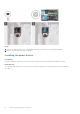
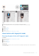
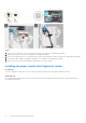
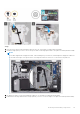
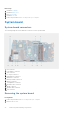

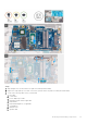
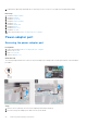
Table Of Contents
- Vostro 15 3510 Service Manual
- Contents
- Working inside your computer
- Removing and installing components
- Recommended tools
- Screw List
- Major components of Vostro 15 3510
- Secure Digital Card
- Base cover
- Battery
- Memory modules
- WLAN card
- Solid-state drive
- Hard drive
- System fan
- Heat sink
- Speakers
- IO board
- Touchpad
- Display assembly
- Hinge caps
- Display bezel
- Hinges
- Display panel
- Camera
- Display eDP cable
- Display back-cover
- Power button
- Power button with fingerprint reader
- System board
- Power-adapter port
- Palm-rest and keyboard assembly
- Drivers and downloads
- System setup
- Troubleshooting
- Getting help and contacting Dell

3. Remove the base cover.
4. Remove the battery.
5. Remove the WLAN card.
6. Remove the memory modules
7. Remove the display assembly.
8. Remove the SSD.
9. Remove the system fan.
10. Remove the heatsink.
NOTE: The system board can be removed along with the heat sink.
About this task
The following images indicate the location of the system board and provides a visual representation of the removal procedure.
Removing and installing components 77