
White Paper


Use Case Study: Using Active System For VMware Cluster Environment Configuration
7
In a LAN-only configuration, the LAN distribution switches have only four types of ports:
Out-of-band management
Stacking ports
Downlinks to the I/O aggregator in the M1000e chassis
Uplinks to the routed network
Downlinks to the I/O aggregators must be configured as LACP-enabled LAGs. LACP must also be enabled
on the LAN distribution switches to allow auto-configuration of downstream I/O aggregators and to tag
network VLANs on the LAGs, since they will be used to configure VLANs on the downstream switch.
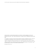
This example shows multiple ports of the Force10 S4810 configured to connect to the I/O Aggregator.
Each port channel is also configured with the appropriate VLANs to carry the environment’s Ethernet
traffic. These ports drive auto-configuration of VLANs on the I/O aggregator LAGs.
LAN-Only Network Diagram
Figure 2.
B2C2 A2B1 C1A1
4
1
7
5
2
8
6
3
9
CMC2CMC1KVM
123456
GbGb 21
CMC
iKVM
GbGb 21
CMC
12
34
CONSOLE
PowerConnect M8024-k
17
18
19
20
12
34
CONSOLE
PowerConnect M8024-k
17
18
19
20
Uplinks from IOA To
LAN Only Distribution
(teal)
Routed Core
Dell M1000e Blade Enclosure
with two PowerEdge M I/O
Aggregators
LAN from Routed Core
OOB Mgmt Connection
LACP Enabled LAG
40GbE Stacking Connections
Uplinks from IOA (teals)
Legend
SYS
PSU
MA
S
T
ER
F
AN
S4810P
0
1
102 4 6 8 12 2214 16 18 20 24 3426 28 30 32 36 4638 40 42 44 48 56
6052
LNK ACT
Ethernet
QSFP+
SFP+
RS-232
SYS
P
SU
MA
S
T
ER
FA
N
S4810P
0
1
102 4 6 8 12 2214 16 18 20 24 3426 28 30 32 36 4638 40 42 44 48 56
6052
LNK ACT
Ethernet
QSFP+
SFP+
RS-232
LAG
LAG
21 22 23 24
LNKACT
Reset
Stack No.
MRPS Fan
P
W
R
S
ta
t
u
s
COMBO PORTS
LNKACT
2 4 6 8 10 12 14 16 18 20 22 24
135 7911 131517192123
Out of Band
Management