
Owner's manual
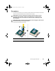

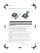


Table Of Contents
- Alienware 17
- Before Working Inside Your Computer
- After Working Inside Your Computer
- Removing the Base Cover
- Replacing the Base Cover
- Removing the Battery
- Replacing the Battery
- Removing the Memory Module(s) 3 and 4
- Replacing the Memory Module(s) 3 and 4
- Removing the Primary Hard Drive
- Replacing the Primary Hard Drive
- Removing the Secondary Hard Drive
- Replacing the Secondary Hard Drive
- Removing the Third Hard Drive (Optional)
- Replacing the Third Hard Drive (Optional)
- Removing the Wireless Mini-Card
- Replacing the Wireless Mini-Card
- Removing the Processor Fan
- Replacing the Processor Fan
- Removing the Video-card Fan
- Replacing the Video-card Fan
- Removing the Processor Heat Sink
- Replacing the Processor Heat Sink
- Removing the Video-Card Heat Sink
- Replacing the Video-Card Heat Sink
- Removing the Video Card
- Replacing the Video Card
- Removing the Palm Rest
- Replacing the Palm Rest
- Removing the Memory Module(s) 1 and 2
- Replacing the Memory Module(s) 1 and 2
- Removing the Keyboard
- Replacing the Keyboard
- Removing the Power-Button Board
- Replacing the Power-Button Board
- Removing the Status-Light Board
- Replacing the Status-Light Board
- Removing the Keyboard Daughter Board
- Replacing the Keyboard Daughter Board
- Removing the Speakers
- Replacing the Speakers
- Removing the I/O Board
- Replacing the I/O Board
- Removing the Media-Card Reader
- Replacing the Media-Card Reader
- Removing the Display Mini-Card
- Replacing the Display Mini-Card
- Removing the Power-Adapter Port
- Replacing the Power-Adapter Port
- Removing the System Board
- Replacing the System Board
- Removing the Coin-Cell Battery
- Replacing the Coin-Cell Battery
- Removing the Processor
- Replacing the Processor
- Removing the Display Assembly
- Replacing the Display Assembly
- Removing the Display Bezel
- Replacing the Display Bezel
- Removing the Display Hinges
- Replacing the Display Hinges
- Removing the Display Panel
- Replacing the Display Panel
- Removing the Logo Board
- Replacing the Logo Board
- Removing the Display Mini-Card Cable
- Replacing the Display Mini-Card Cable
- Removing the Display-Light Boards
- Replacing the Display-Light Boards
- Removing the Camera
- Replacing the Camera
- System Setup
- Flashing the BIOS
Removing the Processor | 91
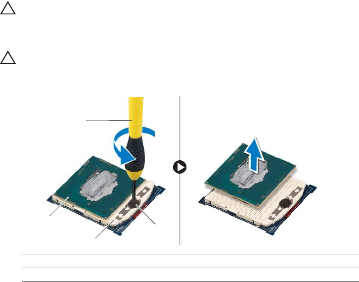
Procedure
1 To loosen the ZIF socket, use a small, flat-blade screwdriver and rotate the ZIF-socket
cam screw counterclockwise until it comes to the cam stop.
CAUTION: To ensure maximum cooling for the processor, do not
touch the heat-transfer areas on the processor or the heat sink.
The oils in your skin can reduce the heat transfer capability of the
thermal pads.
CAUTION: When removing the processor, lift it straight up. Be careful
not to bend the pins on the processor.
2 Lift the processor off the ZIF socket.
1 screwdriver 2 processor
3 ZIF-socket 4 ZIF-socket cam screw
3
4
2
1
book.book Page 91 Friday, June 28, 2013 3:27 PM