
Service Manual


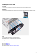

Table Of Contents
- Alienware Aurora R11 Service Manual
- Working inside your computer
- Removing and installing components
- Inside view of your computer
- System-board components
- Recommended tools
- Screw list
- Left-side cover
- Top cover
- Right-side cover
- 2.5-inch hard drive
- 3.5-inch hard drive
- 2.5-inch hard-drive cage
- 3.5-inch hard-drive cage
- 460 W power-supply unit
- 850 W Power-supply unit
- Right tron-light board
- Processor liquid-cooling assembly
- Coin-cell battery
- Memory modules
- Solid-state drive
- Single-graphics card
- Dual-graphics card
- Front bezel
- Top bezel
- Bottom cover
- Processor fan and heat-sink assembly
- Processor
- Wireless card
- Antennas
- Front I/O-panel
- Front-chassis fan
- Top-chassis fan
- Front AlienFX LED boards
- Power-button board
- System board
- Device drivers
- System setup
- Troubleshooting

Installing the top bezel
Prerequisites
If you are replacing a component, remove the existing component before performing the installation procedure.
About this task
The following images indicate the location of the top bezel and provides a visual representation of the installation procedure.
Steps
1. Route the antenna cable through the slots on the chassis.
2. Align the tabs on the top cover with the slots on the chassis and snap the top cover into place.
3. Replace the four screws (#6-32) that secure the top bezel to the right and left of the chassis.
Next steps
1. Install the front bezel.
2. Install the wireless card.
3. Install the right-side cover.
4. Install the
top cover.
67