
Service Manual

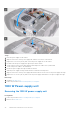
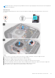
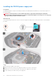

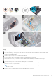
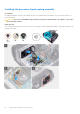
Table Of Contents
- Alienware Aurora R11 Service Manual
- Contents
- Munka a számítógép belsejében
- Alkatrészek eltávolítása és beszerelése
- A számítógép belső nézete
- System-board components
- Ajánlott szerszámok
- Csavarlista
- Bal oldali burkolat
- Felső burkolat
- Jobb oldali burkolat
- 2,5 hüvelykes merevlemez-meghajtó
- 3,5 hüvelykes merevlemez-meghajtó
- 2,5 hüvelykes merevlemezrekesz
- 3,5 hüvelykes merevlemezrekesz
- 550 W power-supply unit
- 1000 W Power-supply unit
- Jobb oldali tron-light kártya
- Processzor folyadékhűtő egység
- Gombelem
- Memóriamodulok
- SSD-meghajtó
- Külön videokártya
- Dupla videokártya
- Elülső keret
- Felső rács
- Alsó burkolat
- Processzorventilátor- és hűtőbordaegység
- Processzor
- Vezeték nélküli kártya
- Antennák
- Előlapi I/O-panel
- Elülső házventilátor
- Felső házventilátor
- Front AlienFX LED boards
- Bekapcsológomb-panel
- Alaplap
- Eszközillesztők
- Rendszerbeállítás
- Hibaelhárítás

NOTE: Az eltávolítás során jegyezze meg a kábelek elvezetését, hogy a tápegység visszaszerelését követően megfelelően
tudja őket visszahelyezni.
About this task
The following images indicate the location of the power-supply unit and provides a visual representation of the removal
procedure.
Steps
1. Remove the two screws (#6-32) that secure the power-supply unit bracket to the power-supply unit cage.
2. Lift the power-supply unit bracket off the power-supply unit cage.
3. Slide the power-supply unit cage release latches to the unlock position.
4. Lift the power-supply unit cage and rotate the power-supply unit cage away from the chassis.
5. Press the releasing clip on the power-cable connectors and disconnect all the power cables from the power-supply unit.
6. Remove the four screws (#6-32) that secure the power-supply unit to the chassis.
7. Slide and lift the power-supply unit, along with the cables, off the chassis.
Alkatrészek eltávolítása és beszerelése
33