Alienware® M11x Service Manual Before You Begin Base Cover Battery Pack Hard-Drive Assembly Memory Module(s) Wireless Mini-Card(s) Hinge Cover Keyboard Palm Rest Assembly Status Light Board Power Button Board Internal Card With Bluetooth® Wireless Technology Coin-Cell Battery Display Assembly I/O Board System Board Speakers Flashing the BIOS Notes, Cautions, and Warnings NOTE: A NOTE indicates important information that helps you make better use of your computer.
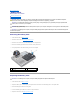
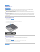
Back to Contents Page Battery Pack Alienware® M11x Service Manual Removing the Battery Pack Replacing the Battery Pack WARNING: Before working inside your computer, read the safety information that shipped with your computer. For additional safety best practices information, see the Regulatory Compliance Homepage at www.dell.com/regulatory_compliance.
Back to Contents Page
Back to Contents Page Before You Begin Alienware® M11x Service Manual Recommended Tools Turning Off Your Computer Before Working Inside Your Computer This manual provides procedures for removing and installing the components in your computer. Unless otherwise noted, each procedure assumes that the following conditions exist: l You have performed the steps in Turning Off Your Computer and Before Working Inside Your Computer. l You have read the safety information that shipped with your computer.
2. Turn off your computer (see Turning Off Your Computer). CAUTION: To disconnect a network cable, first unplug the cable from your computer and then unplug the cable from the network device. 3. Disconnect all telephone or network cables from the computer. 4. Press and eject any installed cards from the 3-in-1 Media Card Reader. 5. Disconnect your computer and all attached devices from their electrical outlets.
Back to Contents Page Flashing the BIOS Alienware® M11x Service Manual 1. Turn on the computer. 2. Go to support.dell.com/support/downloads. 3. Locate the BIOS update file for your computer: NOTE: The Service Tag for your computer is located at the bottom of the computer. If you have your computer's Service Tag: a. Click Enter a Service Tag. b. Enter your computer's Service Tag in the Enter a service tag: field, click Go, and proceed to step 4. If you do not have your computer's Service Tag: a.
Back to Contents Page Base Cover Alienware® M11x Service Manual Removing the Base Cover Replacing the Base Cover WARNING: Before working inside your computer, read the safety information that shipped with your computer. For additional safety best practices information, see the Regulatory Compliance Homepage at www.dell.com/regulatory_compliance.
Back to Contents Page Internal Card With Bluetooth® Wireless Technology Alienware® M11x Service Manual Removing the Bluetooth Card Replacing the Bluetooth Card WARNING: Before working inside your computer, read the safety information that shipped with your computer. For additional safety best practices information, see the Regulatory Compliance Homepage at www.dell.com/regulatory_compliance.
3. Replace the screw that secures the Bluetooth card to the system board. 4. Replace the palm rest assembly (see Replacing the Palm Rest Assembly). 5. Replace the keyboard (see Replacing the Keyboard). 6. Replace the hinge cover (see Replacing the Hinge Cover). 7. Replace the battery pack (see Replacing the Battery Pack). 8. Replace the base cover (see Replacing the Base Cover).
Back to Contents Page Coin-Cell Battery Alienware® M11x Service Manual Removing the Coin-Cell Battery Replacing the Coin-Cell Battery WARNING: Before working inside your computer, read the safety information that shipped with your computer. For additional safety best practices information, see the Regulatory Compliance Homepage at www.dell.com/regulatory_compliance.
4. Replace the palm rest assembly (see Replacing the Palm Rest Assembly). 5. Replace the keyboard (see Replacing the Keyboard). 6. Replace the hinge cover (see Replacing the Hinge Cover). 7. Replace the battery pack (see Replacing the Battery Pack). 8. Replace the base cover (see Replacing the Base Cover). CAUTION: Before turning on the computer, replace all screws and ensure that no stray screws remain inside the computer. Failure to do so may result in damage to the computer.
Back to Contents Page Display Assembly Alienware® M11x Service Manual Removing the Display Assembly Replacing the Display Assembly WARNING: Before working inside your computer, read the safety information that shipped with your computer. For additional safety best practices information, see the Regulatory Compliance Homepage at www.dell.com/regulatory_compliance.
1 display cable connector 12. Gently slide the antenna cables out through the slot on the computer base. 1 2 screws (4) antenna cables 13. Lift the display assembly off the computer. Replacing the Display Assembly 1. Follow the instructions in Before You Begin. 2. Slide the antenna cables in through the slot on the computer base. 3. Place the display assembly in position and replace the four screws that secure the display assembly to the computer base. 4.
Back to Contents Page
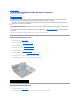
Back to Contents Page Hard-Drive Assembly Alienware® M11x Service Manual Removing the Hard-Drive Assembly Replacing the Hard-Drive Assembly WARNING: If you remove the hard drive from the computer when the drive is hot, do not touch the metal housing of the hard drive. WARNING: Before working inside your computer, read the safety information that shipped with your computer. For additional safety best practices information, see the Regulatory Compliance Homepage at www.dell.com/regulatory_compliance.
7. Remove the four screws that secure the hard drive to the hard-drive bracket. 8. Lift the hard drive away from the hard-drive bracket. 1 screws (4) 3 hard drive 2 hard-drive bracket CAUTION: When the hard drive is not in the computer, store it in protective antistatic packaging (see "Protecting Against Electrostatic Discharge" in the safety instructions that shipped with your computer). Replacing the Hard-Drive Assembly 1. Follow the instructions in Before You Begin. 2.
Back to Contents Page Hinge Cover Alienware® M11x Service Manual Removing the Hinge Cover Replacing the Hinge Cover WARNING: Before working inside your computer, read the safety information that shipped with your computer. For additional safety best practices information, see the Regulatory Compliance Homepage at www.dell.com/regulatory_compliance.
CAUTION: Before turning on the computer, replace all screws and ensure that no stray screws remain inside the computer. Failure to do so may result in damage to the computer.
Back to Contents Page I/O Board Alienware® M11x Service Manual Removing the I/O Board Replacing the I/O Board WARNING: Before working inside your computer, read the safety information that shipped with your computer. For additional safety best practices information, see the Regulatory Compliance Homepage at www.dell.com/regulatory_compliance.
1. Follow the instructions in Before You Begin. 2. Align the connectors on the I/O board with the slots on the computer. 3. Align the connector on the I/O board with the connector on the system board and press gently. 4. Replace the three screws that secure the I/O board to the computer base. 5. Connect the speaker cable to the connector on the I/O board. 6. Replace the palm rest assembly (see Replacing the Palm Rest Assembly). 7. Replace the keyboard (see Replacing the Keyboard). 8.
Back to Contents Page Keyboard Alienware® M11x Service Manual Removing the Keyboard Replacing the Keyboard WARNING: Before working inside your computer, read the safety information that shipped with your computer. For additional safety best practices information, see the Regulatory Compliance Homepage at www.dell.com/regulatory_compliance.
1 screws (2) 3 tabs (5) 2 keyboard 8. Carefully lift the keyboard and slide the keyboard tabs out of the slots on the computer. 9. Without pulling hard on the keyboard, hold it towards the display. 10. Lift the locking tab and pull the pull-tab to disconnect the keyboard cable and backlit keyboard cable from their connectors on the system board. 1 backlit keyboard cable 11. Lift the keyboard off the palm rest assembly. 2 keyboard cable Replacing the Keyboard 1.
CAUTION: Before turning on the computer, replace all screws and ensure that no stray screws remain inside the computer. Failure to do so may result in damage to the computer.
Back to Contents Page Status Light Board Alienware® M11x Service Manual Removing the Status Light Board Replacing the Status Light Board WARNING: Before working inside your computer, read the safety information that shipped with your computer. For additional safety best practices information, see the Regulatory Compliance Homepage at www.dell.com/regulatory_compliance.
1 status light board 2 screws (5) Replacing the Status Light Board 1. Follow the instructions in Before You Begin. 2. Place the status light board on the palm rest assembly and replace the five screws that secure the status light board to the palm rest assembly. 3. Connect the speaker lights cable to the connector on the status light board. 4. Connect the status light board cable to the connector on the status light board and press down on the connector latch to secure the cable. 5.
Back to Contents Page Memory Module(s) Alienware® M11x Service Manual Removing the Memory Module(s) Replacing the Memory Module(s) WARNING: Before working inside your computer, read the safety information that shipped with your computer. For additional safety best practices information, see the Regulatory Compliance Homepage at www.dell.com/regulatory_compliance.
2. Align the notch in the memory module with the tab in the memory module connector. 3. Slide the memory module firmly into the slot at a 45-degree angle, and press the memory module down until it clicks into place. If you do not hear the click, remove the memory module and reinstall it. NOTE: If the memory module is not installed properly, the computer may not boot. 1 tab 3 memory module connector 2 notch 4. Replace the battery pack (see Replacing the Battery Pack). 5.
Back to Contents Page Wireless Mini-Card(s) Alienware® M11x Service Manual Removing the Mini-Card(s) Replacing the Mini-Card(s) WARNING: Before working inside your computer, read the safety information that shipped with your computer. For additional safety best practices information, see the Regulatory Compliance Homepage at www.dell.com/regulatory_compliance.
CAUTION: When the Mini-Card is not in the computer, store it in protective antistatic packaging. For more information, see "Protecting Against Electrostatic Discharge" in the safety information that shipped with your computer. Replacing the Mini-Card(s) 1. Follow the instructions in Before You Begin. 2. Remove the new Mini-Card from its packaging. CAUTION: Use firm and even pressure to slide the card into place. If you use excessive force, you may damage the connector.
Back to Contents Page Palm Rest Assembly Alienware® M11x Service Manual Removing the Palm Rest Assembly Replacing the Palm Rest Assembly WARNING: Before working inside your computer, read the safety information that shipped with your computer. For additional safety best practices information, see the Regulatory Compliance Homepage at www.dell.com/regulatory_compliance.
1 status light board cable connector 3 screws (4) 2 touch pad cable connector 10. Using a plastic scribe carefully pry out the palm rest assembly along the rear edge and then ease the palm rest assembly from the computer base. 11. Hold the palm rest assembly perpendicular to the computer base and disconnect the Alienware logo light cable from the connector on the status light board.
6. Replace the keyboard (see Replacing the Keyboard). 7. Replace the hinge cover (see Replacing the Hinge Cover). 8. Turn the computer over and replace the nine screws that secure the palm rest assembly to the computer base. 9. Replace the battery pack (see Replacing the Battery Pack). 10. Replace the base cover (see Replacing the Base Cover). CAUTION: Before turning on the computer, replace all screws and ensure that no stray screws remain inside the computer.
Back to Contents Page Power Button Board Alienware® M11x Service Manual Removing the Power Button Board Replacing the Power Button Board WARNING: Before working inside your computer, read the safety information that shipped with your computer. For additional safety best practices information, see the Regulatory Compliance Homepage at www.dell.com/regulatory_compliance.
4. Replace the palm rest assembly (see Replacing the Palm Rest Assembly). 5. Replace the keyboard (see Replacing the Keyboard). 6. Replace the hinge cover (see Replacing the Hinge Cover). 7. Replace the battery pack (see Replacing the Battery Pack). 8. Replace the base cover (see Replacing the Base Cover). CAUTION: Before turning on the computer, replace all screws and ensure that no stray screws remain inside the computer. Failure to do so may result in damage to the computer.
Back to Contents Page Speakers Alienware® M11x Service Manual Removing the Speakers Replacing the Speakers WARNING: Before working inside your computer, read the safety information that shipped with your computer. For additional safety best practices information, see the Regulatory Compliance Homepage at www.dell.com/regulatory_compliance.
Back to Contents Page System Board Alienware® M11x Service Manual Removing the System Board Replacing the System Board Entering the Service Tag in the BIOS WARNING: Before working inside your computer, read the safety information that shipped with your computer. For additional safety best practices information, see the Regulatory Compliance Homepage at www.dell.com/regulatory_compliance.
1 system board 3 AC adapter cable connector 2 screws (3) 16. Remove the three screws that secure the system board to the computer base. 17. Carefully ease the connectors on the system board out of the slots in the computer, and lift the system board out of the computer. Replacing the System Board 1. Follow the instructions in Before You Begin. 2. Align the connectors on the system board with the slots on the computer and place it on the computer base. 3.
NOTE: After you have replaced the system board, enter the computer Service Tag into the BIOS of the replacement system board. 19. Enter the service tag (see Entering the Service Tag in the BIOS). Entering the Service Tag in the BIOS 1. Ensure that the AC adapter is plugged in and that the main battery is installed properly. 2. Turn on the computer. 3. Press during POST to enter the system setup program. 4. Navigate to the security tab and enter the service tag in the Set Service Tag field.
Back to Contents Page Alienware® M11x Service Manual NOTE: A NOTE indicates important information that helps you make better use of your computer. CAUTION: A CAUTION indicates potential damage to hardware or loss of data if instructions are not followed. WARNING: A WARNING indicates a potential for property damage, personal injury, or death. Information in this document is subject to change without notice. © 2010 Dell Inc. All rights reserved.