Alienware m15 R2 Service Manual Regulatory Model: P87F Regulatory Type: P87F001 June 2020 Rev.
Notes, cautions, and warnings NOTE: A NOTE indicates important information that helps you make better use of your product. CAUTION: A CAUTION indicates either potential damage to hardware or loss of data and tells you how to avoid the problem. WARNING: A WARNING indicates a potential for property damage, personal injury, or death. © 2019-2020 Dell Inc. or its subsidiaries. All rights reserved. Dell, EMC, and other trademarks are trademarks of Dell Inc. or its subsidiaries.
Contents 1 Safety instructions................................................................................................................................. 5 Before working inside your computer................................................................................................................................. 5 Before you begin ...........................................................................................................................................................
Installing the system board...........................................................................................................................................40 Fan and heat-sink assembly............................................................................................................................................... 44 Removing the fan and heat-sink assembly..................................................................................................................
Safety instructions Use the following safety guidelines to protect your computer from potential damage and to ensure your personal safety. Unless otherwise noted, each procedure included in this document assumes that you have read the safety information that shipped with your computer. NOTE: Before working inside your computer, read the safety information that shipped with your computer. For more safety best practices, see the Regulatory Compliance home page at www.dell.com/regulatory_compliance.
Due to the increased density of semiconductors used in recent Dell products, the sensitivity to static damage is now higher than in previous Dell products. For this reason, some previously approved methods of handling parts are no longer applicable. Two recognized types of ESD damage are catastrophic and intermittent failures. • • Catastrophic – Catastrophic failures represent approximately 20 percent of ESD-related failures. The damage causes an immediate and complete loss of device functionality.
• work surface, and parts should never be placed on top of the ESD bag because only the inside of the bag is shielded. Always place parts in your hand, on the ESD mat, in the system, or inside an anti-static bag. Transporting Sensitive Components – When transporting ESD sensitive components such as replacement parts or parts to be returned to Dell, it is critical to place these parts in anti-static bags for safe transport.
Removing and installing components Recommended tools The procedures in this document may require the following tools: • • • Philips screwdriver #1 Flat-head screwdriver Plastic scribe Screw list NOTE: When removing screws from a component, it is recommended to note the screw type, the quantity of screws, and then place them in a screw storage box. This is to ensure that the correct number of screws and correct screw type is restored when the component is replaced.
Table 1. Screw list(continued) Component Secured to Screw type Quantity Left I/O-board Palm-rest assembly M2x3 1 Right I/O-board connector • • M2x3 2 Right I/O-board Palm-rest assembly M2x3 2 Fans Palm-rest assembly M2.5x5 5 System board Palm-rest assembly M2x3 4 Fan and heat-sink assembly System board M2x3 6 Solid-state drive support bracket Palm-rest assembly M2x1.9 2 Touchpad Palm-rest assembly M2x1.9 4 Solid-state drive support-bracket Palm-rest assembly M2x1.
Steps 1. 2. 3. 4. 5. 6. Remove the two screws (M2.5x5) that secure the base cover to the palm-rest assembly. Loosen the six captive screws. Using a plastic scribe, pry the base cover from the bottom-left corner and continue to work on the sides to open the base cover. Lift the base cover off the palm-rest assembly. Disconnect the battery from the system board. Press and hold the power button for 5 seconds to ground the computer and drain the flea power.
Steps 1. Connect the battery cable to the system board. 2. Slide the notches on the top of the base cover under the rear I/O-cover and snap the base cover into place on the palm-rest assembly.
3. Tighten the six captive screws on the base cover. 4. Replace the two screws (M2.5x5) that secure the base cover to the palm-rest assembly. Next steps 1. Follow the procedure in After working inside your computer. M.2 solid-state drive Removing the M.2 2230 solid-state drive Prerequisites 1. Follow the procedure in Before working inside your computer. 2. Remove the base cover. About this task NOTE: This procedure applies only to computers shipped with a M.2 2230 solid-state drive installed.
Steps 1. 2. 3. 4. 5. Remove the screw (M2x3) that secures the M.2 thermal shield to the mounting bracket. Remove the M.2 2230 thermal shield from the M.2 2230 solid-state drive. Lift and remove the M.2 2230 solid-state drive from the M.2 card slot on the system board. Remove the screw (M2x3) that secures the M.2 2230 mounting bracket to the palm-rest assembly. Remove the M.2 2230 mounting bracket from the palm-rest assembly. Installing the M.
• M.2 2230 solid-state drive + 2230 mounting bracket • M.2 2280 solid-state drive NOTE: For PCIe, NVMe solid-state drives a thermal shield is required for optimal heat dissipation and is installed in the computer when these configurations are ordered. If these configurations are installed After Point-of-Sale (APOS), that is, after you purchase the computer; contact Dell support to purchase a thermal shield. NOTE: Before replacing the M.2 card take note that there are two M.
6. Replace the screw (M2x3) that secures the M.2 2230 solid-state drive and thermal shield to the M.2 2230 mounting bracket. Next steps 1. Install the base cover. 2. Follow the procedure in After working inside your computer. Removing the M.2 2280 solid-state drive Prerequisites 1. Follow the procedure in Before working inside your computer. 2. Remove the base cover. About this task NOTE: This procedure applies only to computers shipped with a M.2 2280 solid-state drive installed.
Installing the M.2 2280 solid-state drive Prerequisites If you are replacing a component, remove the existing component before performing the installation procedure. About this task NOTE: This procedure applies if you are installing a M.2 2280 solid-state drive. NOTE: Depending on the configuration ordered your computer may have up to two M.2 cards installed. Supported card configurations per M.2 card slot: • M.2 2230 solid-state drive + 2230 mounting bracket • M.
Next steps 1. Install the base cover. 2. Follow the procedure in After working inside your computer. Rear-I/O cover Removing the rear I/O-cover Prerequisites 1. Follow the procedure in Before working inside your computer. 2. Remove the base cover. About this task The following image indicates the location of the rear I/O-cover and provides a visual representation of the removal procedure.
Steps 1. Peel and lift the Mylar covering the system board. 2. Disconnect and peel the Tron light cable from the system board and route the cable through the slot on the Mylar. NOTE: To prevent damaging your computer ensure the Tron light cable has been disconnected from the system board before removing the rear I/O-cover. 3. Remove the two screws (M2.5x5) that secure the rear I/O-cover to the palm-rest assembly. 4.
Steps 1. Push the rear I/O-cover into the palm-rest assembly snapping it into place. NOTE: To avoiding damaging your computer, ensure the Tron light cable is not pinched and that the Mylar is pasted on the system board before snapping the rear I/O-cover into place. 2. 3. 4. 5. 6. 7. Replace the two screws (M2.5x5) that secure the rear I/O-cover to the palm-rest assembly. Peel and lift the Mylar from the system board. Route the Tron light cable through the slot on the Mylar.
2. Remove the base cover. 3. Remove the rear I/O-cover. About this task NOTE: The display assembly is a Hinge-up Display (HUD) and cannot be further disassembled. If components within the display assembly need to be replaced, the entire display assembly is to be replaced. The following image indicates the location of the display assembly and provides a visual representation of the removal procedure.
Steps 1. 2. 3. 4. 5. 6. 7. 8. 9. Peel the Mylar covering the system board. Remove the screw (M2x3) that secures the wireless card bracket to the left I/O-board. Lift the wireless card bracket off the left I/O-board. Disconnect the antenna cables from the wireless card. Peel the tapes securing the antenna cables to system board and left fan. Remove the antenna cables from the routing guides on the left fan and system board.
13. Gently lift the display assembly from the palm-rest assembly. Installing the display assembly Prerequisites If you are replacing a component, remove the existing component before performing the installation procedure. About this task NOTE: The display assembly is a Hinge-up Display (HUD) and cannot be further disassembled. If components within the display assembly need to be replaced, the entire display assembly is to be replaced.
Steps 1. Ensure that the palm-rest assembly is placed face up with the keyboard facing you. 2. Gently place the display assembly on the palm-rest assembly and align the screw holes on the display assembly to the screw holes on the palm-rest assembly. 3. Replace the six screws (M2.5x5) that secure the display assembly to the palm-rest assembly. 4. Route the following cables to the routing guides on the palm-rest assembly. • • • • Display cable G-sensor cable Tobii eye tracker cable Antenna cables 5.
11. Connect the antenna cables to the wireless card. The following table provides the antenna-cable color scheme for the wireless card supported by your computer. Table 2. Antenna-cable color scheme Connectors on the wireless card Antenna-cable color Main (white triangle) White Auxiliary (black triangle) Black 12. Place the wireless card bracket on the wireless card. 13. Replace the screw (M2x3) that secures the wireless card bracket to the left I/O-board. 14. Adhere the Mylar over the system board.
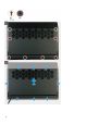
Steps 1. Ensure that the battery cable has been disconnected from the system board. 2. Remove the six screws (M2x4.5) that secure the battery to the palm-rest assembly. 3. Remove the battery from the palm-rest assembly. Installing the battery Prerequisites If you are replacing a component, remove the existing component before performing the installation procedure. About this task The following image indicates the location of the battery and provides a visual representation of the installation procedure.
Coin-cell battery Removing the coin-cell battery Prerequisites CAUTION: Removing the coin-cell battery resets the BIOS setup program’s settings to default. It is recommended that you note the BIOS setup program’s settings before removing the coin-cell battery. 1. 2. 3. 4. 5. Follow the procedure in Before working inside your computer. Remove the base cover. Remove the 2230 solid-state drive. (if applicable) Remove the 2280 solid-state drive. (if applicable) Remove the battery.
Steps 1. 2. 3. 4. Disconnect the coin-cell battery cable from the connector on the system board. Peel the tapes securing the coin-cell battery cable to the right I/O-board and palm-rest assembly. Peel and lift the coin-cell battery off the palm-rest assembly along with its cable. Disconnect the coin-cell battery from the coin-cell battery cable. Installing the coin-cell battery Prerequisites If you are replacing a component, remove the existing component before performing the installation procedure.
3. Adhere the tapes securing the coin-cell battery cable to the right I/O-board and palm-rest assembly. 4. Connect the coin-cell battery cable to the connector on the system board. Next steps 1. 2. 3. 4. 5. Install the battery. Install the 2230 solid-state drive. (if applicable) Install the 2280 solid-state drive. (if applicable) Install the base cover. Follow the procedure in After working inside your computer. Keyboard-controller board Removing the keyboard-controller board Prerequisites 1. 2. 3. 4. 5.
6. Using the plastic tab, pry and remove the keyboard-controller board from the palm-rest assembly. Installing the keyboard-controller board Prerequisites If you are replacing a component, remove the existing component before performing the installation procedure. About this task The following image indicates the location of the keyboard-controller board and provides a visual representation of the installation procedure. Steps 1. 2. 3. 4. 5.
Left I/O-board Removing the left I/O-board Prerequisites 1. 2. 3. 4. 5. Follow the procedure in Before working inside your computer. Remove the base cover. Remove the 2230 solid-state drive. (if applicable) Remove the 2280 solid-state drive. (if applicable) Remove the battery. About this task The following image indicates the location of the left I/O-board and provides a visual representation of the removal procedure. Steps 1. Peel the Mylar covering the system board. 2.
4. 5. 6. 7. 8. 9. Remove the two screws (M2x3) that secure the left I/O-board cable connecting the left I/O-board and the system board. Lift the left I/O-board cable from the left I/O-board and the system board. Disconnect the antenna cables from the wireless card. Lift the latch and disconnect the power-button assembly-cable from the left I/O-board. Remove the screw (M2x3) that secures the left I/O-board to the palm-rest assembly. Lift the left I/O-board off the palm-rest assembly.
3. Connect the power-button assembly-cable to the left I/O-board and close the latch. 4. Connect the antenna cables to the wireless card. The following table provides the antenna-cable color scheme for the wireless card supported by your computer. Table 3. Antenna-cable color scheme Connectors on the wireless card Antenna-cable color Main (white triangle) White Auxiliary (black triangle) Black 5. Using the alignment pins, connect the left I/O-board cable on the left I/O-board and the system board.
Steps 1. 2. 3. 4. 5. 6. Remove the two screws (M2x3) that secure the right I/O-board cable connecting the right I/O-board and the system board. Lift the right I/O-board cable off the right I/O-board and system board. Disconnect the speaker cable from the right I/O-board. Peel the tape securing the coin-cell battery cable to the right I/O-board. Remove the two screws (M2x3) that secure the right I/O-board to the palm-rest assembly. Lift the right I/O-board off the palm-rest assembly.
Steps 1. 2. 3. 4. Using the alignment posts, place the right I/O-board in place on the palm-rest assembly. Replace the two screws (M2x3) that secure the right I/O-board to the palm-rest asssembly. Connect the speaker cable to the connector on the right I/O-board. Using the alignment pins, connect the right I/O-board cable on the right I/O-board and the system board. NOTE: The I/O-board cable is polarity sensitive.
About this task The following image indicates the location of the speakers and provides a visual representation of the removal procedure. Steps 1. 2. 3. 4. Disconnect the speaker cable from the right I/O-board. Lift the right speaker off the palm-rest assembly. Remove the speaker cables from the routing guides on the palm-rest assembly. Lift the left speaker off the palm-rest assembly.
Steps 1. Using the alignment posts, place the left speaker on the palm-rest assembly. NOTE: Ensure that the alignment posts are threaded through the rubber grommets on the speaker. 2. Route the speaker cable through the routing guides on the palm-rest assembly. 3. Using the alignment posts, place the right speaker on the palm-rest assembly. NOTE: Ensure that the alignment posts are threaded through the rubber grommets on the speaker. 4. Connect the speaker cable to the right I/O-board. Next steps 1. 2. 3.
About this task The following image indicates the location of the system board and provides a visual representation of the removal procedure.
Steps 1. Peel the Mylar covering the system board. 2. Remove the screw (M2x3) that secures the wireless card bracket to the left I/O-board. 3. Lift the wireless-card bracket off the left I/O-board. 4. Disconnect the antenna cables from the wireless card. 5. Remove the two screws (M2x3) that secure the left I/O-board cable to the left I/O-board and the system board. 6. Lift the left I/O-board cable off the left I/O-board and the system board. 7.
About this task The following image indicates the location of the system board and provides a visual representation of the removal procedure.
Steps 1. 2. 3. 4. 5. 6. 7. Install the fan and heat-sink assembly. Connect the touchpad cable to the system board and close the latch. Turn the system board over and place the system board on the palm-rest assembly. Replace the five (M2.5x5) screws that secure the fans to the palm-rest assembly. Replace the four (M2x3) screws that secure the system board to the palm-rest assembly. Connect the touchpad cable to the touchpad and close the latch.
NOTE: The I/O-board cable is polarity sensitive. To prevent damage to your computer ensure that the MB UMT end of the cable is connected to the system board. 16. Replace the two screws (M2x3) that secure the left I/O-board cable to the left I/O-board and the system board. 17. Route the antenna cables to the routing guides on the left fan and system board. 18. Adhere the tapes that secure the antenna cables to system board and left fan. 19. Connect the antenna cables to the wireless card.
Steps 1. Disconnect the left and right fan cables from the system board. 2. In the reverse sequential order (6>5>4>3>2>1) remove the six screws (M2x3) that secure the fan and heat-sink assembly to the system board. 3. Lift the fan and heat-sink assembly from the system board.
Installing the fan and heat-sink assembly Prerequisites If you are replacing a component, remove the existing component before performing the installation procedure. CAUTION: If either the processor or the heat sink is replaced, use the thermal grease provided in the kit to ensure that thermal conductivity is achieved. About this task The following image indicates the location of the fan and heat-sink assembly and provides a visual representation of the installation procedure. Steps 1.
Next steps 1. 2. 3. 4. 5. 6. 7. 8. Install the system board. Install the right I/O-board. Install the battery. Install the rear I/O-cover. Install the 2230 solid-state drive. (if applicable) Install the 2280 solid-state drive. (if applicable) Install the base cover. Follow the procedure in After working inside your computer. Touchpad Removing the touchpad Prerequisites 1. 2. 3. 4. 5. 6. 7. 8. Follow the procedure in Before working inside your computer. Remove the base cover.
4. Fold up the keyboard cable. 5. Open the latch and disconnect the touchpad cable from the touchpad. 6. Lift the touchpad cable from the palm-rest assembly. 7. Remove the two (M2x1.9) screws that secure the solid-state drive support bracket to the palm-rest assembly. 8. Lift the solid-state drive support bracket off the palm-rest assembly. 9. Remove the four (M2x1.9) screws that secure the touchpad to the palm-rest assembly. 10. Lift the touchpad off the palm-rest assembly.
Next steps 1. 2. 3. 4. 5. 6. 7. 8. Install the system board. (only applicable when the touchpad cable has been replaced) Install the right I/O-board. (only applicable when the touchpad cable has been replaced) Install the battery. Install the rear I/O-cover. Install the 2230 solid-state drive. (if applicable) Install the 2280 solid-state drive. (if applicable) Install the base cover. Follow the procedure in After working inside your computer.
Installing the power-adapter port Prerequisites If you are replacing a component, remove the existing component before performing the installation procedure. About this task The following image indicates the location of the power-adapter port and provides a visual representation of the installation procedure. Steps 1. Place the power-adapter port into the slot on the palm-rest assembly. 2. Place the power-adapter port bracket on the power-adapter port. 3.
2. 3. 4. 5. 6. 7. 8. 9. Remove the base cover. Remove the 2230 solid-state drive. (if applicable) Remove the 2280 solid-state drive. (if applicable) Remove the rear I/O-cover. Remove the battery. Remove the left I/O-board. Remove the right I/O-board. Remove the system board. About this task The following image indicates the location of the power-button assembly and provides a visual representation of the removal procedure. Steps 1. Remove the three (M2x1.
Steps 1. 2. 3. 4. Place the power-button assembly and its cable in the slot on the palm-rest assembly. Place the power-button bracket on the power-button assembly. Replace the three (M2x1.9) screws that secure the power-button bracket to the palm-rest assembly. Adhere the power-button assembly cable on the palm-rest assembly. Next steps 1. 2. 3. 4. 5. 6. 7. 8. 9. Install the system board. Install the right I/O-board. Install the left I/O-board. Install the battery. Install the rear I/O-cover.
10. Remove the power-button assembly. About this task The following image indicates the location of the keyboard and provides a visual representation of the removal procedure.
Steps 1. 2. 3. 4. 5. 6. 7. Remove the two (M2x1.9) screws that secure the keyboard-backlight cable to the keyboard-controller board. Disconnect the keyboard-backlight cable from the keyboard-controller board. Lift the latch and disconnect the keyboard cable from the keyboard-controller board. Remove the nine (M1.2x2.1) screws that secure the keyboard bracket to the keyboard. Lift the keyboard bracket off the keyboard. Remove the 33 (M1.2x1.6) screws that secure the keyboard to the palm-rest assembly.
Steps 1. 2. 3. 4. 5. 6. 7. Place the keyboard on the palm-rest assembly. Replace the 33 (M1.2x1.6) screws that secure the keyboard to the palm-rest assembly. Place the keyboard bracket on the keyboard. Replace the nine (M1.2x2.1) screws that secure the keyboard bracket to the keyboard. Connect the keyboard cable to the keyboard-controller board and close the latch. Connect the keyboard-backlight cable to the keyboard controller board. Replace the two (M2x1.
Palmrest Removing the palm rest Prerequisites 1. Follow the procedure in Before working inside your computer. 2. Remove the base cover. 3. Remove the 2230 solid-state drive. (if applicable) 4. Remove the 2280 solid-state drive. (if applicable) 5. Remove the rear I/O-cover. 6. Remove the battery. 7. Remove the display assembly. 8. Remove the coin-cell battery. 9. Remove the keyboard-controller board. 10. Remove the left I/O-board. 11. Remove the right I/O-board. 12. Remove the speakers. 13.
Steps To install the palm rest perform the post-requisites. Next steps 1. Install the keyboard. 2. Install the power-button assembly. 3. Install the power-adapter port. 4. Install the touchpad. 5. Install the system board. 6. Install the speakers. 7. Install the right I/O-board. 8. Install the left I/O-board. 9. Install the keyboard-controller board. 10. Install the coin-cell battery. 11. Install the display assembly. 12. Install the battery. 13. Install the rear I/O-cover. 14.
Device drivers Intel Chipset Software Installation Utility In the Device Manager, check if the chipset driver is installed. Install the Intel chipset updates from www.dell.com/support. Video drivers In the Device Manager, check if the video driver is installed. Install the video driver update from www.dell.com/support. Intel Serial IO driver In the Device Manager, check if the Intel Serial IO driver is installed. Install the driver updates from www.dell.com/support.
System setup NOTE: Depending on the computer and its installed devices, the items listed in this section may or may not be displayed. System setup CAUTION: Unless you are an expert computer user, do not change the settings in the BIOS Setup program. Certain changes can make your computer work incorrectly. NOTE: Before you change BIOS Setup program, it is recommended that you write down the BIOS Setup program screen information for future reference.
NOTE: XXX denotes the SATA drive number. • • • Optical Drive (if available) SATA Hard Drive (if available) Diagnostics The boot sequence screen also displays the option to access the System Setup screen. System setup options NOTE: Depending on your computer and its installed devices, the items listed in this section may or may not appear. Table 5. System setup options—Main menu Main System Time Displays the current time in hh:mm:ss format. System Date Displays the current date in mm/dd/yyyy format.
Table 6. System setup options—Advanced menu(continued) Advanced aware operating system, handles USB devices. USB emulation is always enabled during POST. Default: Enabled NOTE: You cannot boot any type of USB device (floppy, hard drive, or memory key) when this option is off. USB Powershare Enables you to charge USB devices when the computer is turned off or in standby mode. Default: Enabled USB Wake Support Enables you to enable the USB devices to wake the computer from Standby.
Table 6. System setup options—Advanced menu(continued) Advanced Auto OS Recovery Threshold Control the automatic boot flow for SupportAssist System Resolution Console and for Dell OS Recovery tool. Default: 2 SupportAssist OS Recovery Enable or disable SupportAssist OS recovery. Default: Enabled Intel(R) Rapid Storage Technology Non-RAID Physical Disks Displays the disk using the Intel(R) Rapid Storage Technology. Table 7.
Table 8. System setup options—Boot menu Boot Boot List Option Displays the available boot options. Default: UEFI File Browser Add Boot Option Enables you to add the boot options. File Browser Del Boot Option Enables you to delete the boot options Secure Boot Enable or disable the secure boot feature. Default: Disabled Legacy Option ROMs Enable or disable the Legacy Option ROMs. Default: Disabled Attempt Legacy Boot Enable or disable Attempt Legacy Boot.
NOTE: For information on how to reset Windows or application passwords, refer to the documentation accompanying Windows or your application.
Troubleshooting Enhanced Pre-Boot System Assessment (ePSA) diagnostics About this task The ePSA diagnostics (also known as system diagnostics) performs a complete check of your hardware. The ePSA is embedded with the BIOS and is launched by the BIOS internally.
Table 10. LED codes(continued) Diagnostic light codes Problem description 2,2 System board: BIOS or ROM (Read-Only Memory) failure 2,3 No memory or RAM (Random-Access Memory) detected 2,4 Memory or RAM (Random-Access Memory) failure 2,5 Invalid memory installed 2,6 System-board or chipset error 2,7 Display failure 2,8 LCD power rail failure.
NOTE: If you do not have the Service Tag, use the auto-detect feature or manually browse for your computer model. 4. 5. 6. 7. 8. 9. Click Drivers & downloads > Find it myself. Select the operating system installed on your computer. Scroll down the page and expand BIOS. Click Download to download the latest version of the BIOS for your computer. After the download is complete, navigate to the folder where you saved the BIOS update file.
Steps 1. Press down on the securing clip that secures the ethernet cable to the RJ-45 port on your computer. 2. With the securing clip held down, pull on the ethernet cable and lift the cable upwards at an angle to release the ethernet cable from the RJ-45 port on your computer. 3. Disconnect the ethernet cable from the RJ-45 port on your computer.
Getting help and contacting Dell Self-help resources You can get information and help on Dell products and services using these self-help resources: Table 11. Self-help resources Self-help resources Resource location Information about Dell products and services www.dell.com My Dell Tips Contact Support In Windows search, type Contact Support, and press Enter. Online help for operating system www.dell.com/support/windows www.dell.