
Service Manual
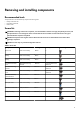
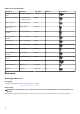

Table 1. Screw list (continued)
Component Secured to Screw type Quantity Screw image
Keyboard-controller
board
Palm-rest assembly M2x1.9 2
Right I/O-board cable
• System board
• Right I/O-board
M2x3 2
Right I/O-board Palm-rest assembly M2x3 2
M.2 solid-state drive
(SSD) frame
System board M2x4.5 3
Fan and heat-sink
assembly
Palm-rest assembly M2x4.5 2
Fan and heat-sink
assembly
Palm-rest assembly M2x3 3
System board Palm-rest assembly M2x3 5
Left I/O-board Palm-rest assembly M2x3 2
Left I/O-board System board M2x4.5 4
Fan and heat-sink
assembly
System board M2x3 10
Power-adapter port
bracket
Palm-rest assembly M2x3 2
Power-button assembly Palm-rest assembly M2x1.9 3
Keyboard bracket Keyboard M1.2x2.1 12
Keyboard Palmrest M1.2x1.6 19
Base cover
Removing the base cover
Prerequisites
1. Follow the procedure in Before working inside your computer.
About this task
NOTE: Before removing the base cover, ensure that there is no micro-SD card installed in the micro-SD card slot on your
computer.
The following image(s) indicate the location of the base cover and provides a visual representation of the removal procedure.
10