
Service Manual

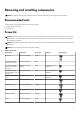
Table Of Contents
- Alienware m17 R4 Service Manual
- Working inside your computer
- Removing and installing components
- Recommended tools
- Screw list
- Major components of Alienware m17 R4
- Base cover
- Solid state drive—M.2 slot one
- Solid state drive—M.2 slot two
- Solid state drive—M.2 slot three
- Battery
- Speakers
- Keyboard-controller board
- Touchpad
- Rear-I/O cover
- Display assembly
- Right I/O-board
- System board
- Left I/O-board
- Fan and heat-sink assembly
- Power-adapter port
- Power-button assembly
- Keyboard
- Palmrest
- Drivers and downloads
- System setup
- Troubleshooting
- Getting help and contacting Alienware

Removing and installing components
NOTE: The images in this document may differ from your computer depending on the configuration you ordered.
Recommended tools
The procedures in this document may require the following tools:
● Phillips screwdriver #0, #1
● Plastic scribe
Screw list
NOTE: When removing screws from a component, it is recommended to note the screw type, the quantity of screws, and then
place them in a screw storage box. This is to ensure that the correct number of screws and correct screw type is restored when
the component is replaced.
NOTE: Some computers have magnetic surfaces. Ensure that the screws are not left attached to such surfaces when replacing a
component.
NOTE: Screw color may vary with the configuration ordered.
Table 1. Screw list
Component Secured to Screw type Quantity Screw image
Base cover Palm-rest assembly M2.5x9 2
M.2 2230 solid-state
drive in M.2 slot three
Palm-rest assembly M2x3 2
M.2 2230 solid-state
drive in M.2 slot one or
M.2 slot two
M.2 2230 mounting
bracket
M2x3 1 per M.2 2230 solid-
state drive
M.2 2230 mounting
bracket in M.2 slot one or
M.2 slot two
Palm-rest assembly M2x3 1 per M.2 2230 solid-
state drive
M.2 2280 solid-state
drive
Palm-rest assembly M2x3 1 per M.2 2280 solid-
state drive
Rear I/O-cover Palm-rest assembly M2.5x5 2
Rear I/O-cover Palm-rest assembly M2x4.5 2
Wireless-card bracket Left I/O-board M2x3 1
Display assembly Palm-rest assembly M2.5x5 6
Battery Palm-rest assembly M2x4 4
9