Alienware m17 R4 サービスマニュアル 規制モデル: P45E 規制タイプ: P45E002 2 月 2021 年 Rev.
メモ、注意、警告 メモ: 製品を使いやすくするための重要な情報を説明しています。 注意: ハードウェアの損傷やデータの損失の可能性を示し、その危険を回避するための方法を説明しています。 警告: 物的損害、けが、または死亡の原因となる可能性があることを示しています。 ©2021 Dell Inc.またはその関連会社。All rights reserved.(不許複製・禁無断転載)Dell、EMC、およびその他の商標は、Dell Inc.
目次 章 1: コンピューター内部の作業................................................................................................................6 PC 内部の作業を始める前に...............................................................................................................................................6 安全にお使いいただくために............................................................................................................................................. 6 ESD(静電気放出)保護..................................................
ディスプレイ アセンブリーの取り外し......................................................................................................................40 ディスプレイ アセンブリーの取り付け...................................................................................................................... 43 右の I/O ボード..................................................................................................................................................................45 右の I/O ボードの取り外し...........................................
BIOS(システム セットアップ)パスワードとシステム パスワードのクリア........................................................84 章 5: トラブルシューティング................................................................................................................ 85 システム診断ライト.......................................................................................................................................................... 85 BIOS のフラッシュ(USB キー).................................................................................................
コンピューター内部の作業 PC 内部の作業を始める前に このタスクについて メモ: 本書の画像は、ご注文の構成によってお使いの PC と異なる場合があります。 手順 1. 開いているファイルをすべて保存してから閉じ、実行中のアプリケーションをすべて終了します。 2. PC をシャットダウンします。 [Start ] > [ Power] > [ Shut down]の順にクリックします。 メモ: 他のオペレーティング システムを使用している場合は、お使いのオペレーティング システムのシャットダウン方法に 関するマニュアルを参照してください。 3. PC および取り付けられているすべてのデバイスをコンセントから外します。 4. キーボード、マウス、モニターなど取り付けられているすべてのネットワークデバイスや周辺機器を PC から外します。 注意: ネットワーク ケーブルを外すには、まずケーブルのプラグを PC から外し、次にケーブルをネットワークデバイスか ら外します。 5.
メモ: お使いの PC の色および一部のコンポーネントは、本書で示されているものと異なる場合があります。 ESD(静電気放出)保護 電気パーツを取り扱う際、ESD は重要な懸案事項です。特に、拡張カード、プロセッサー、メモリ DIMM、およびシステムボード などの静電気に敏感なパーツを取り扱う際に重要です。ほんのわずかな静電気でも、断続的に問題が発生したり、製品寿命が短く なったりするなど、目に見えない損傷が回路に発生することがあります。省電力および高密度設計の向上に向けて業界が前進する 中、ESD からの保護はますます大きな懸念事項となってきています。 最近のデル製品で使用されている半導体の密度が高くなっているため、静電気による損傷の可能性は、以前のデル製品よりも高く なっています。このため、以前承認されていたパーツ取り扱い方法の一部は使用できなくなりました。 ESD による障害には、「致命的」および「断続的」の 2 つの障害のタイプがあります。 ● 致命的 – 致命的な障害は、ESD 関連障害の約 20 %を占めます。障害によりデバイスの機能が完全に直ちに停止します。致命的 な障害の一例としては、静電気
● ● ● ● 首に装着した状態で、リストストラップのボンディングワイヤーをテスターに接続し、ボタンを押してテストを行います。テス ト合格の場合には緑の LED が点灯し、テスト不合格の場合には赤い LED が点灯し、アラームが鳴ります。 絶縁体要素 – プラスチック製のヒートシンクの覆いなど、ESD に敏感なデバイスを、高く帯電していることが多いインシュレ ータ内蔵パーツから遠ざけることが重要です。 作業現場環境 – ESD フィールド・サービス・キットを配備する前に、お客様の場所の状況を評価します。たとえば、サーバ環境用 にキットを配備するのと、デスクトップや携帯デバイス用にキットを配備することは異なります。サーバは通常、データセンタ ー内のラックに設置され、デスクトップや携帯デバイスはオフィスのデスク上か、仕切りで区切られた作業場所に配置されま す。物品が散乱しておらず ESD キットを広げるために十分な平らな広いエリアを探してください。このとき、修理対象のシス テムのためのスペースも考慮してください。また、作業場所に ESD の原因と成り得る絶縁体がないことも確認します。ハード ウェアコンポーネ
4. PC、および取り付けられているすべてのデバイスをコンセントに接続します。 5.
コンポーネントの取り外しと取り付け メモ: 本書の画像は、ご注文の構成によってお使いの PC と異なる場合があります。 推奨ツール この文書で説明する操作には、以下のツールが必要です。 ● プラス ドライバー#0、#1 ● プラスチックスクライブ ネジのリスト メモ: コンポーネントからネジを取り外す際は、ネジの種類、ネジの数量をメモし、その後ネジの保管箱に入れておくことをお 勧めします。これは、コンポーネントを交換する際に正しいネジの数量と正しいネジの種類を保管しておくようにするためで す。 メモ: 一部のコンピューターには、磁性面があります。コンポーネントを交換する際、ネジが磁性面に取り付けられたままにな っていないことを確認してください。 メモ: ネジの色は、発注時の構成によって異なります。 表 1. ネジのリスト コンポーネント 固定先 ネジの種類 数 ベース カバー パームレスト アセンブリ ー M2.5x9 2 M.2 スロット 3 に取り付 けられている M.2 2230 ソリッドステート ドライ ブ パームレスト アセンブリ ー M2x3 2 M.
表 1. ネジのリスト コンポーネント 固定先 ネジの種類 数 ディスプレイ アセンブリ パームレスト アセンブリ ー ー M2.5x5 6 バッテリー パームレスト アセンブリ ー M2x4 4 バッテリー パームレスト アセンブリ ー M2x3 3 左の I/O ボード コネクタ ● システム ボード ー ● 左の I/O ボード M2x4.5 4 左の I/O ボード M2x3 3 右の I/O ボード コネクタ ● システム ボード ー ● 右の I/O ボード M2x3 2 右の I/O ボード パームレスト アセンブリ ー M2x3 3 ファン パームレスト アセンブリ ー M2.5x5 2 システム ボード パームレスト アセンブリ ー M2x3 5 ファンとヒートシンク ア センブリー システム ボード M2x3 10 ソリッドステート ドライ ブ サポート ブラケット パームレスト アセンブリ ー M2x4.5 3 タッチパッド パームレスト アセンブリ ー M2x2.
1. 2. 3. 4.
5. タッチパッド 6. I/O ボードケーブル 7. SSD サポート ブラケット 8. 右の I/O ボード 9. システム ボード 10. キーボードコントローラー ボード 11. スピーカー 12. パーム レスト 13. ディスプレイ アセンブリー 14. 左の I/O ボード 15. キーボード 16. キーボード ブラケット 17. ファンとヒートシンク アセンブリー 18. 電源ボタン アセンブリー 19. 電源ボタン ブラケット 20.電源アダプター ポート 21. 電源アダプター ポートブラケット 22.背面 I/O カバー ベースカバー ベース カバーの取り外し 前提条件 1.
手順 1. ベース カバーをパームレスト アセンブリーに固定している 2 本のネジ(M2.5x9)を外します。 2. 6 本のキャプティブ スクリューを緩めます。 3. プラスチック スクライブを使用して、ネジ穴の周りのすき間からベース カバーをこじ開けて、ベース カバーのクリップをパーム レスト アセンブリーから外します。 4. 両サイドを持って、ベース カバーをこじ開けます。 5. ベースカバーを持ち上げて、パームレストアセンブリーから取り外します。 6. バッテリーをシステム ボードから外します。 メモ: バッテリー ケーブルは、PC から引き続き他のコンポーネントも取り外す場合にのみ取り外してください。 7.
手順 1. 必要に応じて、バッテリーケーブルをシステム ボードに接続します。 2. ベース カバーの上部の切り込みを背面 I/O カバーの下にスライドさせ、ベース カバーをパームレスト アセンブリーの所定の位置 にはめ込みます。 3. ベース カバー上の 6 本のキャプティブ スクリューを締めます。 4. ベース カバーをパームレスト アセンブリーに固定する 2 本のネジ(M2.5x9)を取り付けます。 次の手順 1. 「PC 内部の作業を終えた後に」の手順に従います。 ソリッド ステート ドライブ:M.2 スロット 1 2280 ソリッドステート ドライブを M.2 スロット 1 から取り外す 前提条件 1. 『PC 内部の作業を始める前に』の手順に従います。 2. ベース カバーを取り外します。 このタスクについて メモ: この手順は、M.
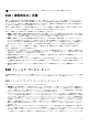
メモ: 発注時の構成に応じて、お使いの PC は、M.2 スロット 1 の 2230 ソリッドステート ドライブまたは 2280 ソリッドステ ート ドライブのいずれかをサポートする場合があります。 次の画像は、M.2 スロット 1 に取り付けられている 2280 ソリッドステート ドライブの位置を示すもので、取り外し手順を視覚的 に表しています。 手順 1. ソリッドステート ドライブのサーマル シールドをパームレスト アセンブリーに固定しているネジ(M2x3)を外します。 メモ: サーマル シールドは、ソリッドステート ドライブの容量が 512 GB 以上の場合にのみ取り付けられています。 2. ソリッドステート ドライブのサーマル シールドを持ち上げて、M.2 2280 ソリッドステート ドライブから取り外します。 3. M.2 2280 ソリッドステート ドライブをスライドさせて、システム ボードの M.2 カード スロットから取り外します。 2280 ソリッドステート ドライブを M.
手順 1. M.2 2280 ソリッドステート ドライブの切り込みをシステム ボードの M.2 カード スロットのタブに合わせます。 2. M.2 2280 ソリッドステート ドライブをシステム ボードの M.2 カード スロットに差し込みます。 メモ: 次の手順は、ソリッドステート ドライブの容量が 512 GB 以上の場合にのみ適用されます。 3. ソリッドステート ドライブのサーマル シールドをスライドさせて、ネジ穴をパームレスト アセンブリーのネジ穴に合わせます。 4. M.2 2280 ソリッドステート ドライブをパームレスト アセンブリーに固定するネジ(M2x3)を取り付けます。 次の手順 1. ベースカバーを取り付けます。 2. 「PC 内部の作業を終えた後に」の手順に従います。 2230 ソリッドステート ドライブを M.2 スロット 1 から取り外す 前提条件 1. 『PC 内部の作業を始める前に』の手順に従います。 2. ベース カバーを取り外します。 このタスクについて メモ: この手順は、M.
手順 1. ソリッドステート ドライブのサーマル シールドを M.2 2230 マウント ブラケットに固定しているネジ(M2x3)を取り外しま す。 メモ: サーマル シールドは、ソリッドステート ドライブの容量が 512 GB 以上の場合にのみ取り付けられています。 2. ソリッドステート ドライブのサーマル シールドを、M.2 2230 ソリッドステート ドライブから取り外します。 3. M.2 2230 ソリッドステート ドライブを持ち上げて、システム ボードの M.2 カード スロットから取り外します。 4. M.2 2230 マウント ブラケットをパームレスト アセンブリーに固定しているネジ(M2x3)を外します。 5. M.2 2230 マウント ブラケットを持ち上げて、パームレスト アセンブリーから取り外します。 M.2 2230 ソリッドステート ドライブを M.2 スロット 1 から取り付ける 前提条件 コンポーネントを交換する場合、取り付け手順を実行する前に、既存のコンポーネントを取り外してください。 このタスクについて メモ: この手順は、M.
メモ: 発注時の構成に応じて、お使いの PC は、M.2 スロット 1 の 2230 ソリッドステート ドライブまたは 2280 ソリッドステ ート ドライブのいずれかをサポートする場合があります。 メモ: ソリッドステート ドライブの容量が 512 GB 以上の場合は、最適な放熱のために、サーマル シールドが必要になります。 PC を購入した後に、より高い設定のソリッドステート ドライブを取り付けた場合は、Dell サポートに連絡して、サーマル シー ルドを購入してください。 次の画像は、M.2 スロット 1 に取り付けられている 2230 ソリッドステート ドライブの位置を示すもので、取り付け手順を視覚的 に表しています。 手順 1. M.2 2230 マウント ブラケットをパームレスト アセンブリーにセットして位置を合わせます。 2. M.2 2230 マウント ブラケットをパームレスト アセンブリーに固定するネジ(M2x3)を取り付けます。 3. M.2 2230 ソリッドステート ドライブの切り込みをシステム ボードの M.2 カード スロットのタブに合わせます。 4. M.
次の手順 1. ベースカバーを取り付けます。 2. 「PC 内部の作業を終えた後に」の手順に従います。 ソリッド ステート ドライブ:M.2 スロット 2 2280 ソリッドステート ドライブを M.2 スロット 2 から取り外す 前提条件 1. 『PC 内部の作業を始める前に』の手順に従います。 2. ベース カバーを取り外します。 このタスクについて メモ: この手順は、M.2 スロット 2 に取り付けられた 2280 ソリッドステート ドライブが搭載されている PC にのみ適用されま す。 メモ: 発注時の構成に応じて、お使いの PC は、M.2 スロット 2 の 2230 ソリッドステート ドライブまたは 2280 ソリッドステ ート ドライブのいずれかをサポートする場合があります。 次の画像は、M.2 スロット 2 に取り付けられている 2280 ソリッドステート ドライブの位置を示すもので、取り外し手順を視覚的 に表しています。 手順 1.
2280 ソリッドステート ドライブを M.2 スロット 2 から取り付ける 前提条件 コンポーネントを交換する場合、取り付け手順を実行する前に、既存のコンポーネントを取り外してください。 このタスクについて メモ: この手順は、M.2 スロット 2 に 2280 ソリッドステート ドライブを取り付ける場合に適用されます。 メモ: 発注時の構成に応じて、お使いの PC は、M.2 スロット 2 の 2230 ソリッドステート ドライブまたは 2280 ソリッドステ ート ドライブのいずれかをサポートする場合があります。 メモ: ソリッドステート ドライブの容量が 512 GB 以上の場合は、最適な放熱のために、サーマル シールドが必要になります。 PC を購入した後に、より高い設定のソリッドステート ドライブを取り付けた場合は、Dell サポートに連絡して、サーマル シー ルドを購入してください。 次の画像は、M.2 スロット 2 に取り付けられている 2280 ソリッドステート ドライブの位置を示すもので、取り付け手順を視覚的 に表しています。 手順 1. M.
2230 ソリッドステート ドライブを M.2 スロット 2 から取り外す 前提条件 1. 『PC 内部の作業を始める前に』の手順に従います。 2. ベース カバーを取り外します。 このタスクについて メモ: この手順は、M.2 スロット 2 に取り付けられた 2230 ソリッドステート ドライブが搭載されている PC にのみ適用されま す。 メモ: 発注時の構成に応じて、お使いの PC は、M.2 スロット 2 の 2230 ソリッドステート ドライブまたは 2280 ソリッドステ ート ドライブのいずれかをサポートする場合があります。 次の画像は、M.2 スロット 2 に取り付けられている 2230 ソリッドステート ドライブの位置を示すもので、取り外し手順を視覚的 に表しています。 手順 1. ソリッドステート ドライブのサーマル シールドを M.
メモ: サーマル シールドは、ソリッドステート ドライブの容量が 512 GB 以上の場合にのみ取り付けられています。 2. ソリッドステート ドライブのサーマル シールドを、M.2 2230 ソリッドステート ドライブから取り外します。 3. M.2 2230 ソリッドステート ドライブを持ち上げて、システム ボードの M.2 カード スロットから取り外します。 4. M.2 2230 マウント ブラケットをパームレスト アセンブリーに固定しているネジ(M2x3)を外します。 5. M.2 2230 マウント ブラケットを持ち上げて、パームレスト アセンブリーから取り外します。 2230 ソリッドステート ドライブを M.2 スロット 2 から取り付ける 前提条件 コンポーネントを交換する場合、取り付け手順を実行する前に、既存のコンポーネントを取り外してください。 このタスクについて メモ: この手順は、M.2 スロット 2 に 2230 ソリッドステート ドライブを取り付ける場合に適用されます。 メモ: 発注時の構成に応じて、お使いの PC は、M.
手順 1. M.2 2230 マウント ブラケットをパームレスト アセンブリーにセットして位置を合わせます。 2. M.2 2230 マウント ブラケットをパームレスト アセンブリーに固定するネジ(M2x3)を取り付けます。 3. M.2 2230 ソリッドステート ドライブの切り込みをシステム ボードの M.2 カード スロットのタブに合わせます。 4. M.2 2230 ソリッドステート ドライブをシステム ボードの M.2 カード スロットに差し込みます。 5. ソリッドステート ドライブのサーマル シールドを、M.2 2230 ソリッドステート ドライブにスライドさせます。 メモ: 次の手順は、ソリッドステート ドライブの容量が 512 GB 以上の場合にのみ適用されます。 6. M.2 2230 ソリッドステート ドライブとソリッドステート ドライブのサーマル シールドを M.2 2230 マウント ブラケットに固 定する 2 本のネジ(M2x3)を取り付けます。 次の手順 1. ベースカバーを取り付けます。 2.
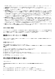
ソリッド ステート ドライブ:M.2 スロット 3 2230 ソリッドステート ドライブを M.2 スロット 3 から取り外す 前提条件 1. 「PC 内部の作業を始める前に」の手順に従います。 2. ベース カバーを取り外します。 このタスクについて メモ: M.2 スロット 3 は、2230 ソリッドステート ドライブのみをサポートします。 次の画像は、M.2 スロット 3 に取り付けられている 2230 ソリッドステート ドライブの位置を示すもので、取り外し手順を視覚的 に表しています。 手順 1. ソリッドステート ドライブのサーマル シールドを左の I/O ボードに固定している 2 本のネジ(M2x3)を外します。 メモ: サーマル シールドは、ソリッドステート ドライブの容量が 512 GB 以上の場合にのみ取り付けられています。 2. ソリッドステート ドライブのサーマル シールドを、M.2 2230 ソリッドステート ドライブから取り外します。 3. M.2 2230 ソリッドステート ドライブを左の I/O ボードの M.
メモ: ソリッドステート ドライブの容量が 512 GB 以上の場合は、最適な放熱のために、サーマル シールドが必要になります。 PC を購入した後に、より高い設定のソリッドステート ドライブを取り付けた場合は、Dell サポートに連絡して、サーマル シー ルドを購入してください。 次の画像は、M.2 スロット 3 に取り付けられている 2230 ソリッドステート ドライブの位置を示すもので、取り付け手順を視覚的 に表しています。 手順 1. M.2 2230 ソリッドステート ドライブの切り込みを、左の I/O ボードの M.2 カード スロットのタブに合わせます。 2. M.2 2230 ソリッドステート ドライブを、左の I/O ボードの M.2 カード スロットに差し込みます。 メモ: 次の手順は、ソリッドステート ドライブの容量が 512 GB 以上の場合にのみ適用されます。 3. ソリッドステート ドライブのサーマル シールドを、M.2 2230 ソリッドステート ドライブ上にセットします。 4. M.
● バッテリを高温にさらしたり、バッテリ パックまたはセルを分解したりしないでください。 ● バッテリの表面に圧力をかけないでください。 ● バッテリを曲げないでください。 ● 種類にかかわらず、ツールを使用してバッテリをこじ開けないでください。 ● バッテリやその他のシステム コンポーネントの偶発的な破裂や損傷を防ぐため、この製品のサービス作業中に、ネジを紛 失したり置き忘れたりしないようにしてください。 ● 膨張によってリチウムイオン バッテリがコンピュータ内で詰まってしまう場合、穴を開けたり、曲げたり、押しつぶした りすると危険なため、無理に取り出そうとしないでください。そのような場合は、デル テクニカル サポートにお問い合わ せください。www.dell.com/contactdell を参照してください。 ● 必ず、www.dell.com または Dell 認定パートナーおよび再販業者から正規のバッテリを購入してください。 バッテリーの取り外し 前提条件 1. 『PC 内部の作業を始める前に』の手順に従います。 2.
3. バッテリーをパームレスト アセンブリーに固定している 3 本のネジ(M2x3)を取り外します。 4. バッテリーを持ち上げて、パームレスト アセンブリーから取り外します。 バッテリーの取り付け 前提条件 コンポーネントを交換する場合、取り付け手順を実行する前に、既存のコンポーネントを取り外してください。 このタスクについて 次の図は、バッテリの場所を示すもので、取り付け手順を視覚的に表しています。 手順 1. バッテリをパームレスト アセンブリーにセットします。 2. バッテリーをパームレスト アセンブリーに固定する 3 本のネジ(M2x3)を取り付けます。 3. バッテリーをパームレストアセンブリーに固定する 4 本のネジ(M2x4)を取り付けます。 4. バッテリーケーブルをシステム ボードに接続します。 次の手順 1. ベースカバーを取り付けます。 2. 「PC 内部の作業を終えた後に」の手順に従います。 スピーカー スピーカーの取り外し 前提条件 1. 『PC 内部の作業を始める前に』の手順に従います。 2.
このタスクについて 以下の画像はスピーカーの場所を示すもので、取り外し手順を視覚的に表しています。 手順 1. スピーカー ケーブルを右の I/O ボードから外します。 2. 右スピーカーを持ち上げて、パームレストアセンブリーから取り外します。 3. スピーカー ケーブルをパームレスト アセンブリーの配線ガイドから外します。 4.
手順 1. 位置合わせポストを使用して、左スピーカーをパームレストアセンブリーにセットします。 メモ: パームレストとキーボード アセンブリーの位置合わせポストが、スピーカーのゴム製グロメットに通されていることを 確認します。 メモ: スピーカーを取り外す際にゴム製グロメットがスピーカーから押し出された場合は、スピーカーの取り付け前に押し戻 します。 2. スピーカーケーブルをパームレストアセンブリーの配線ガイドに沿って配線します。 3. 位置合わせポストを使用して、右スピーカーをパームレストアセンブリーにセットします。 メモ: パームレストとキーボード アセンブリーの位置合わせポストが、スピーカーのゴム製グロメットに通されていることを 確認します。 メモ: スピーカーを取り外す際にゴム製グロメットがスピーカーから押し出された場合は、スピーカーの取り付け前に押し戻 します。 4. スピーカー ケーブルを右の I/O ボードに接続します。 次の手順 1. ベースカバーを取り付けます。 2.
このタスクについて 以下の画像はキーボードコントローラー ボードの位置を示すもので、取り外し手順を視覚的に表しています。 手順 1. ラッチを開いて、キーボードバックライト ケーブルをキーボードコントローラー ボードから外します。 2. ラッチを開き、キーボードコントローラー ボード ケーブルをキーボードコントローラー ボードから外します。 3. ラッチを開いて、キーボード ケーブルをキーボードコントローラー ボードから外します。 4. キーボードコントローラー ボードをパームレスト アセンブリーに固定している 2 本のネジ(M2x1.9)を外します。 5.
手順 1. 調節ピンを使用して、キーボードコントローラー ボードをパームレスト アセンブリーの所定の位置にセットします。 2. キーボードコントローラー ボードのネジ穴を、パームレスト アセンブリーのネジ穴に合わせます。 3. キーボードコントローラー ボード ケーブルをキーボードコントローラー ボードに接続し、ラッチを閉じます。 4. キーボード ケーブルをキーボードコントローラー ボードに接続し、ラッチを閉じます。 5. キーボードバックライト ケーブルをキーボードコントローラー ボードに接続し、ラッチを閉じます。 6. キーボードコントローラー ボードをパームレスト アセンブリーに固定する 2 本のネジ(M2x1.9)を取り付けます。 次の手順 1. バッテリーを取り付けます。 2. ベース カバーを取り付けます。 3. 「PC 内部の作業を終えた後に」の手順に従います。 タッチパッド タッチパッドの取り外し 前提条件 1. 『PC 内部の作業を始める前に』の手順に従います。 2. ベース カバーを取り外します。 3.
手順 1. ラッチを開いて、キーボードコントローラー ボードケーブルをキーボードコントローラー ボードから外します。 2. ラッチを開いて、キーボードコントローラー ボードケーブルをシステム ボードから外します。 3. キーボードコントローラー ボードケーブルを持ち上げ、パームレスト アセンブリーから外します。 4. ラッチを開いて、キーボード ケーブルをキーボードコントローラー ボードから外します。 5. キーボード ケーブルを折りたたみます。 6. ラッチを開いて、タッチパッド ケーブルをタッチパッドから外します。 7. タッチパッドケーブルを持ち上げて、パームレスト アセンブリーから外します。 8. タッチパッドをパームレスト アセンブリーに固定している 4 本のネジ(M2x2.5)を外します。 9. タッチパッドをパームレスト アセンブリーに固定しているテープをはがします。 10.
このタスクについて 以下の画像はタッチパッドの場所を示すもので、取り付け手順を視覚的に表しています。 手順 1. タッチパッドをパームレスト アセンブリーのスロットにセットします。 メモ: PC を表向きに置いて、ディスプレイを開きます。タッチパッドが 4 つのすべての面に沿って均等に合っていること を確認します。 2. タッチパッドをパームレスト アセンブリーに固定する 4 本のネジ(M2x2.5)を取り付けます。 3. タッチパッドをパームレスト アセンブリーに固定するテープを貼り付けます。 4. タッチパッド ケーブルをタッチパッドに接続し、ラッチを閉じます。 メモ: このステップは、タッチパッド ケーブルが取り付けられていない場合にのみ適用されます。 5. キーボード ケーブルを折りたたみます。 6. キーボード ケーブルをキーボードコントローラー ボードに接続し、ラッチを閉じます。 7. キーボードコントローラー ボード ケーブルをキーボードコントローラー ボードに接続し、ラッチを閉じます。 8.
次の手順 1. バッテリーを取り付けます。 2. ベースカバーを取り付けます。 3. 「PC 内部の作業を終えた後に」の手順に従います。 背面 I/O カバー 背面 I/O カバーの取り外し 前提条件 1. 「PC 内部の作業を始める前に」の手順に従います。 2.
手順 1. システム ボードを覆っているマイラー シートをはがして、取り除きます。 2. トロンライト ケーブルをシステム ボードから外してはがします。 注意: PC の損傷を防ぐため、背面 I/O カバーを取り外す前に、トロンライト ケーブルがシステム ボードから外れているこ とを確認します。 3. 背面 I/O カバーをパームレスト アセンブリーに固定している 2 本のネジ(M2.5x5)を外します。 4. 背面 I/O カバーをパームレスト アセンブリーに固定している 2 本のネジ(M2x4.5)を外します。 5. 両手で PC の側面をしっかりとつかみ、親指で背面 I/O カバーのラバー フィートを外側に向けて押し、背面 I/O カバーをパーム レスト アセンブリーから外せるようにします。 6.
手順 1. マイラー シートをシステム ボードの所定の位置に貼り付けます。 2. 背面 I/O カバーをパームレスト アセンブリーに押し込んで、所定の位置にはめ込みます。 メモ: PC の損傷を防ぐため、背面 I/O カバーを所定の位置にはめ込む前に、トロン ライト ケーブルが挟まれてないこと、 およびマイラー シートがシステム ボードに貼り付けられていることを確認してください。 3. 背面 I/O カバーをパームレスト アセンブリーに固定する 2 本のネジ(M2x4.5)を取り付けます。 4. 背面 I/O カバーをパームレスト アセンブリーに固定する 2 本のネジ(M2.5x5)を取り付けます。 5. トロン ライト ケーブルをシステム ボードに接続します。 6. トロン ライト ケーブルを配線し、マイラー シートの下にあるシステム ボード上の所定の位置に貼り付けます。 次の手順 1. ベースカバーを取り付けます。 2. 「PC 内部の作業を終えた後に」の手順に従います。 ディスプレイアセンブリ ディスプレイ アセンブリーの取り外し 前提条件 1.
手順 1. ワイヤレス カード ブラケットを左の I/O ボードに固定しているネジ(M2x3)を外します。 2. ワイヤレス カード ブラケットを持ち上げて、左の I/O ボードから取り外します。 3. アンテナケーブルをワイヤレスカードから外します。 4. アンテナ ケーブルをシステム ボードと左側ファンに固定しているテープを剥がします。 5. アンテナ ケーブルを左側ファンとシステム ボードの配線ガイドから外します。 6. モニター ケーブルをシステム ボードに固定しているテープをはがします。 7. ラッチを開いて、モニター ケーブルをシステム ボードのコネクターから外します。 8. G センサー ケーブルをシステム ボードのコネクターから外します。 9. システム ボード上のコネクターから Tobii アイ トラッカー ケーブルを外します。 メモ: このステップは、Tobii アイ トラッカーが付属する PC にのみ適用されます。 10. PC の表を上にして置きます。 注意: ディスプレイを傷付けないように、PC を柔らかく、清潔な面に置きます。 11.
● アンテナ ケーブル 12. ディスプレイ アセンブリーをパームレスト アセンブリーに固定している 6 本のネジ(M2.5x5)を外します。 13.
手順 1. パームレスト アセンブリーが、キーボードと共に上向けにセットされていることを確認します。 2. ディスプレイ アセンブリーをパームレスト アセンブリーに慎重にセットし、ディスプレイ アセンブリーのネジ穴をパームレスト アセンブリーのネジ穴の位置に合わせます。 3. ディスプレイアセンブリーをパームレストアセンブリーに固定する 6 本のネジ(M2.5x5)を取り付けます。 4. 次のケーブルをパームレスト アセンブリーの配線ガイドに沿って配線します。 ● ● ● ● モニター ケーブル G センサー ケーブル Tobii アイ トラッカー ケーブル(オプション) アンテナ ケーブル 5. PC の表を下にして置きます。 6. Tobii アイ トラッカー ケーブルをシステム ボードのコネクターに接続します。 メモ: このステップは、Tobii アイ トラッカーが付属する PC にのみ適用されます。 7. G センサー ケーブルをシステム ボードのコネクターに接続します。 8. モニター ケーブルをシステム ボードのコネクターに接続し、ラッチを閉じます。 9.
11. アンテナケーブルをワイヤレスカードに接続します。 次の表に、お使いの PC がサポートするワイヤレス カード用アンテナケーブルの色分けを示します。 表 2. アンテナケーブルの色分け ワイヤレスカードのコネクター アンテナケーブルの色 メイン(白色の三角形) 白色または灰色 補助(黒色の三角形) 黒色または橙色 12. ワイヤレス カード ブラケットをワイヤレス カードにセットします。 13. ワイヤレス カード ブラケットを左の I/O ボードに固定するネジ(M2x3)を取り付けます。 次の手順 1. 背面 I/O カバーを取り付けます。 2. ベース カバーを取り付けます。 3. 「PC 内部の作業を終えた後に」の手順に従います。 右の I/O ボード 右の I/O ボードの取り外し 前提条件 1. 2. 3. 4. 5. 『PC 内部の作業を始める前に』の手順に従います。 ベース カバーを取り外します。 バッテリーを取り外します。 取り付けられている場合、M.2 スロット 2 にある 2230 ソリッドデート ドライブを取り外します。 取り付けられている場合、M.
手順 1. システム ボードと右の I/O ボードを覆うマイラー シートを持ち上げます。 2. 右の I/O ボードとシステム ボードに接続している右の I/O ボード ケーブルを固定している 2 本のネジ(M2x3)を外します。 3. 右の I/O ボード ケーブルを持ち上げて、右の I/O ボードとシステム ボードから外します。 4. スピーカー ケーブルを右の I/O ボードから外します。 5. 右の I/O ボードをパームレスト アセンブリーに固定している 3 本のネジ(M2x3)を外します。 6.
手順 1. 右の I/O ボードをパームレスト アセンブリーにセットします。 2. 右の I/O ボードのネジ穴をパームレスト アセンブリーのネジ穴に合わせます。 3. 右の I/O ボードをパームレスト アセンブリーに固定する 3 本のネジ(M2x3)を取り付けます。 4. スピーカー ケーブルを右の I/O ボードのコネクターに接続します。 5. 調節ピンを使用して、右の I/O ボード ケーブルを右の I/O ボードとシステム ボードに接続します。 メモ: I/O ボード ケーブルは極性に敏感です。PC の損傷を防ぐため、ケーブルの MB UMT の端がシステム ボードに接続さ れていることを確認してください。 6. 右の I/O ボード ケーブルを右の I/O ボードとシステム ボードに固定する 2 本のネジ(M2x3)を取り付けます。 次の手順 1. 2. 3. 4. 5. 取り付けられていた場合、M.2 スロット 2 に 2280 ソリッドステート ドライブを取り付けます。 取り付けられていた場合、M.
システム ボード システム ボードの取り外し 前提条件 1. 2. 3. 4. 5. 6. 7. 8. 「PC 内部の作業を始める前に」の手順に従います。 ベース カバーを取り外します。 取り付けられている場合、M.2 スロット 1 にある 2230 ソリッドステート ドライブを取り外します。 取り付けられている場合、M.2 スロット 1 にある 2280 ソリッドステート ドライブを取り外します。 取り付けられている場合、M.2 スロット 2 にある 2230 ソリッドステート ドライブを取り外します。 取り付けられている場合、M.
手順 1. ワイヤレス カード ブラケットを左の I/O ボードに固定しているネジ(M2x3)を外します。 2. ワイヤレスカード ブラケットを持ち上げて、左の I/O ボードから取り外します。 3. アンテナケーブルをワイヤレスカードから外します。 4. アンテナ ケーブルをシステム ボードと左側ファンに固定しているテープを剥がします。 5. アンテナ ケーブルを、左のファンの配線ガイドから外します。 6. ラッチを開いて、電源ボタン ケーブルを左の I/O ボードから外します。 7. ラッチを開き、タッチパッド ケーブルをシステム ボードから外します。 8. ラッチを開いて、キーボードコントローラー ボードケーブルをシステム ボードから外します。 9. ソリッドステート ドライブ サポート ブラケットをシステム ボードに固定している 3 本のネジ(M2x4.5)を外します。 10. ソリッドステート ドライブ サポート ブラケットをシステム ボードから取り外します。 11. 右の I/O ボード ケーブルを右の I/O ボードとシステム ボードに固定している 2 本のネジ(M2x3)を外します。 12.
メモ: このステップは、Tobii アイ トラッカーが付属する PC にのみ適用されます。 17. ファンをパームレスト アセンブリーに固定している 2 本のネジ(M2.5x5)を外します。 18. システム ボードをパームレスト アセンブリーに固定している 5 本のネジ(M2x3)を外します。 19. 左の I/O ボードをパームレスト アセンブリーに固定している 3 本のネジ(M2x3)を外します。 20.システム ボードと左の I/O ボードを持ち上げて、パームレスト アセンブリーから取り外します。 メモ: システム ボードを持ち上げる際には、ファンとヒートシンク アセンブリーの両側をしっかりとつかんで支えてくださ い。 注意: PC の損傷を防ぐため、システム ボードを持ち上げる際には、左の I/O ボードでシステム ボードを支えないでくださ い。 21. システム ボードを裏返します。 22.左の I/O ボードを取り外します。 23.
手順 1. ファンとヒートシンク アセンブリーを取り付けます。 2. 左の I/O ボードを取り付けます。 3. システム ボードを裏返し、システム ボードと左の I/O ボードをパームレスト アセンブリー上にセットします。 メモ: システム ボードを所定の位置にセットする際には、ファンとヒートシンク アセンブリーの両側をしっかりとつかんで 支えてください。 注意: PC の損傷を防ぐため、システム ボードをセットする際には、左の I/O ボードでシステム ボードを支えないでくださ い。 4. ファンをパームレスト アセンブリーに固定する 2 本のネジ(M2.5x5)を取り付けます。 5. システム ボードをパームレスト アセンブリーに固定する 5 本のネジ(M2x3)を取り付けます。 6. 左の I/O ボードをパームレスト アセンブリーに固定する 3 本のネジ(M2x3)を取り付けます。 7. Tobii アイ トラッカー ケーブルをシステム ボードのコネクターに接続します。 メモ: このステップは、Tobii アイ トラッカーが付属する PC にのみ適用されます。 8.
11. 調節ピンを使用して、右の I/O ボード ケーブルを右の I/O ボードとシステム ボードに接続します。 メモ: I/O ボード ケーブルは極性に敏感です。PC の損傷を防ぐため、ケーブルの MB UMT の端がシステム ボードに接続さ れていることを確認してください。 12. 右の I/O ボード ケーブルを右の I/O ボードとシステム ボードに固定する 2 本のネジ(M2x3)を取り付けます。 13. ソリッドステート ドライブ サポート ブラケットのタブとシステム ボードのスロットを使用して、ソリッドステート ドライブ サ ポート ブラケットのネジ穴をシステム ボードのネジ穴に合わせます。 14. ソリッドステート ドライブ サポート ブラケットをシステム ボードに固定する 3 本のネジ(M2x4.5)を取り付けます。 15. キーボードコントローラー ボードケーブルをシステム ボードに接続し、ラッチを閉じます。 16. タッチパッド ケーブルをシステム ボードに接続し、ラッチを閉じます。 17. 電源ボタンケーブルをシステム ボードに接続します。 18.
このタスクについて 注意: インターポーザー ボードは、左の I/O ボードとシステム ボードの間に取り付けられています。左の I/O ボードを取り外 してすぐにインターポーザー ボードを取り外し、清潔で安全な場所に保管します。インターポーザー ボード上のピンは壊れや すいため、ボードを持ち上げて、端をつかみます。 以下の画像は左の I/O ボードの位置を示すもので、取り外し手順を視覚的に表しています。 手順 1. 左の I/O ボードをシステム ボードに固定している 4 本のネジ(M2x4.5)を取り外します。 2. 左の I/O ボードを持ち上げて、システム ボードから取り外します。 3.
手順 1. 調節ピンを使用して、インターポーザー ボードをシステム ボードにセットします。 2. 調節ピンを使用して、左の I/O ボードをインターポーザー ボードを通してシステム ボードに接続します。 3. 左の I/O ボードのネジ穴を、システム ボードとインターポーザー ボードのネジ穴に合わせます。 4. 左の I/O ボードをシステム ボードに固定する 4 本のネジ(M2x4.5)を取り付けます。 次の手順 1. 2. 3. 4. 5. 6. 7. 8. 9. 『システム ボードの取り付け』の手順 3~22 に従ってください。 バッテリーを取り付けます。 背面 I/O カバーを取り付けます。 取り付けられていた場合、M.2 スロット 2 に 2280 ソリッドステート ドライブを取り付けます。 取り付けられていた場合、M.2 スロット 2 に 2230 ソリッドステート ドライブを取り付けます。 取り付けられていた場合、M.2 スロット 1 に 2280 ソリッドステート ドライブを取り付けます。 取り付けられていた場合、M.
9.
手順 1. 左右のファン ケーブルをシステム ボードから外します。 2. シーケンシャルな順序(10>9>8>7>6>5>4>3>2>1)で、ファンとヒート シンク アセンブリーをシステム ボードに固定して いる 10 本のネジ(M2x3)を外します。 メモ: ネジの数は、発注時の構成によって異なります。 3.
手順 1. ファンとヒートシンク アセンブリーをシステム ボードにセットします。 2. シーケンシャルな順序(1>2>3>4>5>6>7>8>9>10)で、ファンとヒート シンク アセンブリーをシステム ボードに固定する 10 本のネジ(M2x3)を取り付けます。 メモ: ネジの数は、発注時の構成によって異なります。 3.
次の手順 1. 2. 3. 4. 5. 6. 7. 8. 9. 『システム ボードの取り付け』の手順 3~22 に従ってください。 バッテリーを取り付けます。 背面 I/O カバーを取り付けます。 取り付けられていた場合、M.2 スロット 2 に 2280 ソリッドステート ドライブを取り付けます。 取り付けられていた場合、M.2 スロット 2 に 2230 ソリッドステート ドライブを取り付けます。 取り付けられていた場合、M.2 スロット 1 に 2280 ソリッドステート ドライブを取り付けます。 取り付けられていた場合、M.2 スロット 1 に 2230 ソリッドステート ドライブを取り付けます。 ベースカバーを取り付けます。 「PC 内部の作業を終えた後に」の手順に従います。 電源アダプタポート 電源アダプターポートの取り外し 前提条件 1. 2. 3. 4. 5. 6. 7. 8. 9. 『PC 内部の作業を始める前に』の手順に従います。 ベース カバーを取り外します。 取り付けられている場合、M.
2. 電源アダプター ポート ブラケットを持ち上げて、パームレスト アセンブリーから取り外します。 3. 電源アダプター ポートをケーブルと一緒に持ち上げて、パームレストアセンブリーから取り外します。 電源アダプター ポートの取り付け 前提条件 コンポーネントを交換する場合、取り付け手順を実行する前に、既存のコンポーネントを取り外してください。 このタスクについて 以下の画像は電源アダプター ポートの場所を示すもので、取り付け手順を視覚的に表しています。 手順 1. 電源アダプター ポートをパームレストアセンブリーのスロットにセットします。 2. 電源アダプター ポートブラケットを電源アダプター ポートにセットします。 3. 電源アダプター ポート ブラケットをパームレスト アセンブリーに固定する 2 本のネジ(M2x3)を取り付けます。 次の手順 1. 2. 3. 4. 5. 6. 7. 8. 9. 60 『システム ボードの取り付け』の手順 3~22 に従ってください。 バッテリーを取り付けます。 背面 I/O カバーを取り付けます。 取り付けられていた場合、M.
電源ボタン アセンブリー 電源ボタン アセンブリーの取り外し 前提条件 1. 『PC 内部の作業を始める前に』の手順に従います。 2. ベース カバーを取り外します。 3. 取り付けられている場合、M.2 スロット 1 にある 2230 ソリッドステート ドライブを取り外します。 4. 取り付けられている場合、M.2 スロット 1 にある 2280 ソリッドステート ドライブを取り外します。 5. 取り付けられている場合、M.2 スロット 2 にある 2230 ソリッドステート ドライブを取り外します。 6. 取り付けられている場合、M.2 スロット 2 にある 2280 ソリッドステート ドライブを取り外します。 7. 背面 I/O カバーを取り外します。 8. バッテリーを取り外します。 9. 右の I/O ボードを取り外します。 10. 『システム ボードの取り外し』の手順 1~21 に従ってください。 このタスクについて 以下の画像は電源ボタン アセンブリーの位置を示すもので、取り外し手順を視覚的に表しています。 手順 1.
このタスクについて 以下の画像は電源ボタン アセンブリーの位置を示すもので、取り付けの手順を視覚的に表しています。 手順 1. 電源ボタン アセンブリーとそのケーブルをパームレスト アセンブリーのスロットにセットします。 2. 電源ボタン ブラケットを電源ボタン アセンブリーにセットします。 3. 電源ボタン ブラケットをパームレスト アセンブリーに固定する 2 本のネジ(M2x1.9)を取り付けます。 次の手順 1. 『システム ボードの取り付け』の手順 3~22 に従ってください。 2. 右の I/O ボードを取り付けます。 3. バッテリーを取り付けます。 4. 背面 I/O カバーを取り付けます。 5. 取り付けられていた場合、M.2 スロット 2 に 2280 ソリッドステート ドライブを取り付けます。 6. 取り付けられていた場合、M.2 スロット 2 に 2230 ソリッドステート ドライブを取り付けます。 7. 取り付けられていた場合、M.2 スロット 1 に 2280 ソリッドステート ドライブを取り付けます。 8. 取り付けられていた場合、M.
6. 取り付けられている場合、M.2 スロット 2 にある 2280 ソリッドステート ドライブを取り外します。 7. 背面 I/O カバーを取り外します。 8. バッテリーを取り外します。 9. 右の I/O ボードを取り外します。 10.
手順 1. ラッチを開いて、キーボードバックライト ケーブルをキーボードコントローラー ボードから外します。 2. ラッチを開いて、キーボード ケーブルをキーボードコントローラー ボードから外します。 3. キーボード ブラケットをキーボードに固定している 10 本のネジ(M1.2x2.1)を外します。 4. キーボードブラケットを持ちあげてキーボードから取り外します。 5. キーボードをパームレスト アセンブリーに固定している 28 本のネジ(M1.2x1.6)を外します。 6.
手順 1. キーボードをパームレストアセンブリーにセットします。 2. キーボードをパームレスト アセンブリーに固定する 28 本のネジ(M1.2x1.6)を取り付けます。 メモ: 28 本のネジ穴は矢印で示されています。 3. キーボード ブラケットをキーボードにセットします。 4. キーボード ブラケットをキーボードに固定する 10 本のネジ(M1.2x2.1)を取り付けます。 5. キーボード ケーブルをキーボードコントローラー ボードに接続し、ラッチを閉じます。 6. キーボードバックライト ケーブルをキーボードに接続し、ラッチを閉じます。 次の手順 1. 『システム ボードの取り付け』の手順 3~22 に従ってください。 2. 右の I/O ボードを取り付けます。 3. バッテリーを取り付けます。 4. 背面 I/O カバーを取り付けます。 5. 取り付けられていた場合、M.2 スロット 2 に 2280 ソリッドステート ドライブを取り付けます。 6. 取り付けられていた場合、M.2 スロット 2 に 2230 ソリッドステート ドライブを取り付けます。 7. 取り付けられていた場合、M.
8. バッテリーを取り外します。 9. 右の I/O ボードを取り外します。 10.
手順 1. ラッチを開いて、キーボードバックライト ケーブルをキーボードコントローラー ボードから外します。 2. ラッチを開いて、キーボード ケーブルをキーボードコントローラー ボードから外します。 3. キーボード ブラケットをキーボードに固定している 15 本のネジ(M1.2x2.5)を外します。 4. キーボードブラケットを持ちあげてキーボードから取り外します。 5. メカニカル キーボードをパームレスト アセンブリーに固定している 25 本のネジ(M1.2x2)を外します。 メモ: 25 本のネジ穴は矢印で示されています。 6.
手順 1. メカニカル キーボードをパームレスト アセンブリーにセットします。 2. メカニカル キーボードをパームレスト アセンブリーに固定する 25 本のネジ(M1.2x2)を取り付けます。 メモ: 25 本のネジ穴は矢印で示されています。 3. キーボード ブラケットをキーボードにセットします。 4. キーボード ブラケットをキーボードに固定する 15 本のネジ(M1.2x2.5)を取り付けます。 5. キーボード ケーブルをキーボードコントローラー ボードに接続し、ラッチを閉じます。 6. キーボードバックライト ケーブルをキーボードに接続し、ラッチを閉じます。 次の手順 1. 『システム ボードの取り付け』の手順 3~22 に従ってください。 2. 右の I/O ボードを取り付けます。 3. バッテリーを取り付けます。 4. 背面 I/O カバーを取り付けます。 5. 取り付けられていた場合、M.2 スロット 2 に 2280 ソリッドステート ドライブを取り付けます。 6. 取り付けられていた場合、M.2 スロット 2 に 2230 ソリッドステート ドライブを取り付けます。 7.
パーム レストの取り付け 前提条件 コンポーネントを交換する場合、取り付け手順を実行する前に、既存のコンポーネントを取り外してください。 手順 パーム レストを取り付けるために、「作業を終えた後に」を実行します。 次の手順 1.
2. 電源ボタン アセンブリーを取り付けます。 3. 電源アダプター ポートを取り付けます。 4. タッチパッドを取り付けます。 5. 『システム ボードの取り付け』の手順 3~22 に従ってください。 6. 右の I/O ボードを取り付けます。 7. キーボードコントローラー ボードを取り付けます。 8. ディスプレイ アセンブリーを取り付けます。 9. バッテリーを取り付けます。 10. 背面 I/O カバーを取り付けます。 11. スピーカーを取り付けます。 12. 取り付けられていた場合、M.2 スロット 2 に 2280 ソリッドステート ドライブを取り付けます。 13. 取り付けられていた場合、M.2 スロット 2 に 2230 ソリッドステート ドライブを取り付けます。 14. 取り付けられていた場合、M.2 スロット 1 に 2280 ソリッドステート ドライブを取り付けます。 15. 取り付けられていた場合、M.2 スロット 1 に 2230 ソリッドステート ドライブを取り付けます。 16. ベースカバーを取り付けます。 17.
ドライバおよびダウンロード ドライバのトラブルシューティング、ダウンロードまたはインストールを行うときには、Dell ナレッジベースの記事「ドライバおよ びダウンロードに関するよくあるお問い合わせ」(SLN128938)を読むことが推奨されます。 73
システム セットアップ 注意: PC に詳しいユーザー以外は、BIOS セットアップ プログラムの設定を変更しないでください。特定の変更で PC が誤作 動を起こす可能性があります。 メモ: PC および取り付けられているデバイスによっては、本項にリスト表示されている項目の一部がない場合があります。 メモ: BIOS セットアップ プログラムを変更する前に、後で参照できるように、BIOS セットアップ プログラム画面の情報を控 えておくことをお勧めします。 BIOS セットアップ プログラムは次の目的で使用します。 ● RAM の容量やハード ドライブのサイズなど、PC に取り付けられているハードウェアに関する情報の取得。 ● システム設定情報の変更。 ● ユーザー パスワード、取り付けられたハード ドライブの種類、基本デバイスの有効化または無効化など、ユーザー選択可能オプ ションの設定または変更。 BIOS セットアッププログラムの起動 手順 1. PC の電源をオンにします。 2.
ワンタイム ブート メニューでは診断オプションを含むオプションから起動可能なデバイスを表示します。起動メニューのオプショ ンは以下のとおりです。 ● リムーバブルドライブ(利用可能な場合) ● STXXXX ドライブ(利用可能な場合) メモ: XXX は、SATA ドライブの番号を意味します。 ● 光学ドライブ(利用可能な場合) ● SATA ハード ドライブ(利用可能な場合) ● 診断 メモ: [Diagnostics(診断)]を選択すると [ePSA 診断] 画面が表示されます。 ブート シーケンス画面ではセットアップ画面にアクセスするオプションを表示することも可能です。 システム セットアップのオプション メイン 表 5.
表 6.
表 6.
セキュリティ 表 7.
表 7. セキュリティ オプション 説明 管理者以外のセットアップ の変更 管理者パスワードが設定されている場合に、セットアップオプションの変更を許可するかどうかを 決めることができます。無効に設定すると、セットアップオプションは管理者パスワードによって ロックされます。 ● [ワイヤレス スイッチの変更を許可する] このオプションは、デフォルトでは設定されていません。 UEFI カプセル ファームウ ェアのアップデート システム BIOS を UEFI カプセル アップデート パッケージでアップデートすることができます。 ● [UEFI カプセル ファームウェアのアップデートを有効にする] このオプションはデフォルトで有効化されています。 TPM 2.
表 8. セキュア ブート オプション 説明 セキュア ブート セキュア ブート機能を有効または無効にします。 いずれかのオプションを選択します。 ● [セキュア ブートを有効にする] ● [セキュア ブートを無効にする] デフォルト:Enabled レガシー オプション ROM レガシー オプション ROM を有効または無効にします。 デフォルト:Disabled レガシー起動試行 レガシー起動試行を有効または無効にします。 デフォルト:Disabled 起動オプションの優先順位 ブート シーケンスを表示します。 起動オプション#1 利用可能な最初の起動オプションを表示します。 起動オプション#2 利用可能な 2 番目の起動オプションを表示します。 起動オプション#3 利用可能な 3 番目の起動オプションを表示します。 セキュア ブート 表 9.
Windows での BIOS のアップデート 前提条件 システム ボードを交換する場合やアップデートが入手できる場合は、BIOS(セットアップ ユーティリティ)をアップデートするこ とをお勧めします。ノートパソコンの場合、お使いの PC のバッテリがフル充電されていて電源に接続されていることを確認して ください。 このタスクについて メモ: BitLocker が有効になっている場合は、システム BIOS をアップデートする前に一時停止し、BIOS のアップデート完了後 に再度有効にする必要があります。 手順 1. PC を再起動します。 2. www.dell.com/support にアクセスします。 ● [サービス タグ]または[エクスプレス サービス コード]を入力し、[検索]をクリックします。 ● [Drivers & Downloads](ドライバおよびダウンロード)をクリックします。 ● ドライバーを検出をクリックして、画面の指示に従います。 3. サービス タグを検出または検索できない場合は、[すべての製品を参照]をクリックします。 4.
手順 1. BIOS アップデート.exe ファイルを別の PC にダウンロードします。 2. .exe ファイルをブート可能 USB フラッシュ ドライブにコピーします。 3. BIOS のアップデートを必要とする PC に、USB フラッシュ ドライブを挿入します。 4. PC を再起動し、デルのロゴが表示されたら F12 を押して、ワン タイム ブート メニューを表示します。 5. 矢印キーを使用して、[USB ストレージ デバイス]を選択し、 [Enter]を押します。 6. PC が起動し、Diag C:\>プロンプトが表示されます。 7. 完全なファイル名を入力して[Enter]を押し、ファイルを実行します。 8. BIOS アップデート ユーティリティーが表示されます。画面の指示に従います。 F12 ワンタイム ブート メニューからの BIOS のフラッシ ュ FAT32 USB ドライブにコピーされた BIOS update.
注意: BIOS のアップデート プロセス中に PC の電源をオフにしないでください。PC の電源をオフにすると、PC が起動しな い場合があります。 手順 1. 電源オフの状態から、フラッシュをコピーした USB ドライブを PC の USB ポートに挿入します。 2. PC の電源をオンにして F12 を押し、ワンタイム ブート メニューにアクセスした後、マウスまたは矢印キーを使用して[BIOS アップデート]を選択し、Enter を押します。 フラッシュ BIOS メニューが表示されます。 3. [[ファイルからフラッシュ]]をクリックします。 4. 外部 USB デバイスを選択します。 5. ファイルを選択してフラッシュ ターゲット ファイルをダブルクリックした後、[送信]をクリックします。 6. [BIOS のアップデート]をクリックします。PC が再起動して、BIOS をフラッシュします。 7. BIOS のアップデートが完了すると、PC が再起動します。 システムパスワードおよびセットアップパスワード 表 10.
既存のシステム セットアップパスワードの削除または変更 前提条件 既存のシステム パスワードおよび/またはセットアップ パスワードを削除または変更しようとする前に、[パスワード ステータス]が (システム セットアップで)ロック解除になっていることを確認します。パスワード ステータスがロックされている場合は、既存 のシステム パスワードやセットアップ パスワードを削除または変更できません。 このタスクについて システム セットアップを起動するには、電源投入または再起動の直後に F12 を押します。 手順 1. [システム BIOS]画面または[システム セットアップ]画面で、[システム セキュリティ]を選択し、Enter を押します。 System Security(システムセキュリティ)画面が表示されます。 2. システムセキュリティ画面でパスワードステータスがロック解除に設定されていることを確認します。 3. [システム パスワード]を選択し、既存のシステム パスワードをアップデートまたは削除して、Enter または Tab を押します。 4.
トラブルシューティング システム診断ライト 電源およびバッテリーステータスライト 電源およびバッテリー ステータス ライトは、PC の電源とバッテリーの状態を示しています。電源の状態は次のとおりです。 ソリッド ホワイト:電源アダプターが接続され、バッテリーの充電量は 5%を超えています。 橙色:PC はバッテリーで作動しており、バッテリーの充電量は 5%未満です。 消灯: ● 電源アダプターに接続されており、バッテリーはフル充電されています。 ● PC がバッテリーで作動しており、バッテリーの充電量は 5%を超えています。 ● PC がスリープ状態、休止状態、または電源オフです。 電源およびバッテリーステータス ライトは、事前に定義された「ビープ コード」にしたがって赤色または青色に点滅することにより、 さまざまな障害を示す場合があります。 例えば、電源およびバッテリーステータスライトが、赤色に 2 回点滅して停止し、次に青色に 3 回点滅して停止します。この 2、3 のパターンは、PC の電源がオフになるまで続き、メモリーまたは RAM が検出されないことを示しています。 次の表には、さまざまな電源および
表 11. 診断ライト LED コード 診断ライト コード(赤、 青) 問題の内容 推奨される解決策 3,5 母線の障害です EC で電源シーケンス障害が発生しました。問題が解決 しない場合は、システム ボードを交換します。 3,6 システム BIOS のフラッシュが不完全です SBIOS によってフラッシュの破損が検出されました。 問題が解決しない場合は、システム ボードを交換しま す。 3,7 マネジメント・エンジン(ME)エラー ME が HECI メッセージへの返信を待機している間にタ イムアウトしました。問題が解決しない場合は、システ ム ボードを交換します。 BIOS のフラッシュ(USB キー) 手順 1. BIOS のフラッシュ」の手順 1 から 7 に従って、最新の BIOS セットアップ プログラム ファイルをダウンロードします。 2. 起動可能な USB ドライブを作成します。詳細については、www.dell.com/support でナレッジベース記事 SLN143196 を参照し てください。 3.
バックアップ メディアとリカバリー オプション Windows で発生する可能性がある問題のトラブルシューティングと修正のために、回復ドライブを作成することが推奨されていま す。デルでは、Dell PC の Windows オペレーティング システムをリカバリするために、複数のオプションを用意しています。詳細 に関しては「デルの Windows バックアップ メディアおよびリカバリ オプション」を参照してください。 Wi-Fi 電源の入れ直し このタスクについて お使いのコンピューターが Wi-Fi 接続の問題が原因でインターネットにアクセスできない場合は、Wi-Fi 電源の入れ直し手順を実施 することができます。次に、Wi-Fi 電源の入れ直しの実施方法についての手順を示します。 メモ: 一部の ISP(インターネット サービス プロバイダ)はモデム/ルータ コンボ デバイスを提供しています。 手順 1. コンピュータの電源を切ります。 2. モデムの電源を切ります。 3. ワイヤレス ルータの電源を切ります。 4. 30 秒待ちます。 5. ワイヤレス ルータの電源を入れます。 6.
「困ったときは」と「Alienware へのお問い合わせ」 セルフヘルプリソース オンライン セルフヘルプ リソースを使って Alienware の製品とサービスに関するヘルプ情報を取得できます。 表 12. Alienware 製品とオンライン セルフヘルプ リソース セルフヘルプリソース リソースの場所 Alienware 製品とサービスに関する情報は、 www.alienware.com Dell のヘルプとサポート アプリ ヒント お問い合わせ Windows サーチに、 [ヘルプとサポート ]と入力し、[Enter ] を押します。 オペレーティング システムのオンライン ヘルプ www.dell.com/support/windows トラブルシューティング情報、ユーザーズガイド、セットアップ www.alienware.com/gamingservices 方法、製品仕様、テクニカルサポートブログ、ドライバ、ソフ トウェアのアップデートなどは お使いのコンピュータの保守に関する段階的な手順が分かるビ デオは、 www.youtube.