Alienware M17x R4 Owner’s Manual Computer model: M17x R4 Regulatory model: P11E Regulatory type: P11E002
Notes, Cautions, and Warnings NOTE: A NOTE indicates important information that helps you make better use of your computer. CAUTION: A CAUTION indicates potential damage to hardware or loss of data if instructions are not followed. WARNING: A WARNING indicates a potential for property damage, personal injury, or death. ____________________ Information in this document is subject to change without notice. © 2012 Dell Inc. All rights reserved.
Contents 1 Before You Begin . . . . . . . . . . . . . . . . . . . . Turn Off Your Computer and Connected Devices. Safety Instructions . . . . . . . . . . . . . . . . . . . . Recommended Tools. . . . . . . . . . . . . . . . . . . 2 3 Removing the Battery Pack . . . . . . . . . . . . . . . . . . . . . . . . . . . . 12 Replacing the Battery Pack . . . . . . . . . . . . . . . . . . . . . . . . . . 13 13 . . . . . . . . . . . . . . . . . . . . . . . . . . . . . . . . . . . . . . . . . . . . . . . . .
10 Replacing the Hard Drive(s) . Procedure . . . Postrequsites 11 21 . . . . . . . . . . . . . . . . . . . . . . . . . 21 21 . . . . . . . . . . . . . . . . . . . . . . . . . Removing the Memory Module(s) . . . . 22 Prerequsites Procedure . . 12 . . . . . . . . . . . . . . . . . . . . . . . . . . . . . . . . . . . . . . . . . . . . . . . . . . . . . . . . . . . . . Replacing the Memory Module(s) . . . . 24 Procedure . . . Postrequsites . . . . . . . . . . . . . . . . . . . . . . . . . . . . . . .
18 Replacing the Graphics-Card Assembly Procedure . . . Postrequsites 34 . . . . . . . . . . . . . . . . . . . . . . . . . . . . . . . . . . . . . . . . . . . . . . . . . . 19 Removing the Processor Heat-Sink Prerequsites Procedure . . 35 . . . . . . . . . . . . . . . . . . . . . . . . . . . . . . . . . . . . . . . . . . . . . . . . . . . . 20 Replacing the Processor Heat-Sink Procedure . . . Postrequsites 21 35 36 37 . . . . . . . . . . . . . . . . . . . . . . . . . . . . . . . . . . . . . . . .
26 Replacing the Keyboard . Procedure . . . Postrequsites . . . . . . . . . . . . . . . . . . . . . . . . . . . . . . . . . . . . . . . . . . . . . . . . . . 27 Removing the Mini-Card . Prerequsites Procedure . . . . . . . . . . . . . . . . . . . . . . . . . . . . . . . . . . . . . . . . . . . . . . . . . . . . . . . . . . . . . . . . . . . . . . . . . . . . 28 Replacing the Mini-Card Procedure . . . Postrequsites 51 52 . . . . . . . . . . . . . . . . . . . . . . . . . . . . . . . . . . . . . . . .
34 Replacing the Display Assembly Procedure . . . Postrequsites 60 . . . . . . . . . . . . . . . . . . . . . . . . . . . . . . . . . . . . . . . . . . . . . . . . . . 35 Removing the Status Light Board Prerequsites Procedure . . 61 . . . . . . . . . . . . . . . . . . . . . . . . . . . . . . . . . . . . . . . . . . . . . . . . . . . . 36 Replacing the Status Light Board Procedure . . . Postrequsites . . . . . . . . . . . . . . . . . . . . . . . . . . . . . . . . . . . . . . . . . . . . . . . . . . .
Postrequsites . . . . . . . . . . . . . . . . . . . . . . . . . 43 Removing the Optical Drive Prerequsites Procedure . . . . . . . . . . . . . . . . . . . . . . . . . . . . . . . . . . . . . . . . . . . . . . . . . . . . . . . . . . . . . . 44 Replacing the Optical Drive Procedure . . . Postrequsites . . . . . . . . . . . . . . . . . . . . . . . . . . . . . . . . . . . . . . . . . . . . . . . . . . . . . . . . . . . 45 Removing the System Board. Prerequsites Procedure . . 76 76 76 . . . . . . . .
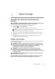
Before You Begin 1 Turn Off Your Computer and Connected Devices CAUTION: To avoid losing data, save and close all open files and exit all open programs before you turn off your computer. 1 Save and close all open files and exit all open programs. 2 Click Start and click Shut down. Microsoft Windows shuts down and then the computer turns off. NOTE: If you are using a different operating system, see the documentation of your operating system for shut-down instructions.
CAUTION: Only a certified service technician is authorized to remove the computer cover and access any of the components inside the computer. See the safety instructions for complete information about safety precautions, working inside your computer, and protecting against electrostatic discharge. CAUTION: Before touching anything inside your computer, ground yourself by touching an unpainted metal surface, such as the metal at the back of the computer.
2 After Working Inside Your Computer After you complete replacement procedures, ensure the following: • • Replace all screws and ensure that no stray screws remain inside your computer • Connect your computer and all attached devices to their electrical outlets Connect any external devices, cables, cards, and any other part(s) you removed before working on your computer CAUTION: Before turning on your computer, replace all screws and ensure that no stray screws remain inside the computer.
Removing the Battery Pack 3 WARNING: Before working inside your computer, read the safety information that shipped with your computer and follow the steps in "Before You Begin" on page 9. For additional safety best practices information, see the Regulatory Compliance Homepage at dell.com/ regulatory_compliance. Procedure 1 Slide the battery latch to the unlock position as shown. The battery pack pops up. 2 Remove the battery pack.
4 Replacing the Battery Pack WARNING: Before working inside your computer, read the safety information that shipped with your computer and follow the steps in "Before You Begin" on page 9. For additional safety best practices information, see the Regulatory Compliance Homepage at dell.com/ regulatory_compliance. Procedure CAUTION: To avoid damage to the computer, use only the battery designed for this particular Alienware computer.
Removing the Compartment Door 5 WARNING: Before working inside your computer, read the safety information that shipped with your computer and follow the steps in "Before You Begin" on page 9. For additional safety best practices information, see the Regulatory Compliance Homepage at dell.com/ regulatory_compliance. Prerequsites Remove the battery pack. See "Removing the Battery Pack" on page 12. Procedure 1 Remove the screws that secure the compartment door to the computer base.
6 Replacing the Compartment Door WARNING: Before working inside your computer, read the safety information that shipped with your computer and follow the steps in "Before You Begin" on page 9. For additional safety best practices information, see the Regulatory Compliance Homepage at dell.com/ regulatory_compliance. Procedure 1 Align the tabs on the compartment door with the slots on the computer base and slide the compartment door into place.
Removing the Coin-Cell Battery 7 WARNING: Before working inside your computer, read the safety information that shipped with your computer and follow the steps in "Before You Begin" on page 9. For additional safety best practices information, see the Regulatory Compliance Homepage at dell.com/ regulatory_compliance. Prerequsites 1 Remove the battery pack. See "Removing the Battery Pack" on page 12. 2 Remove the compartment door. See "Removing the Compartment Door" on page 14.
8 Replacing the Coin-Cell Battery WARNING: Before working inside your computer, read the safety information that shipped with your computer and follow the steps in "Before You Begin" on page 9. For additional safety best practices information, see the Regulatory Compliance Homepage at dell.com/ regulatory_compliance. Procedure 1 Hold the coin-cell battery with the positive side facing up. 2 Slide the coin-cell battery into the slot and gently press until it snaps into place.
Removing the Hard Drive(s) 9 WARNING: Before working inside your computer, read the safety information that shipped with your computer and follow the steps in "Before You Begin" on page 9. For additional safety best practices information, see the Regulatory Compliance Homepage at dell.com/ regulatory_compliance. WARNING: If you remove the hard drive from the computer when the drive is hot, do not touch the metal housing of the hard drive.
Primary hard-drive assembly 1 2 1 captive screws (3) 2 primary hard-drive assembly Secondary hard-drive assembly 2 1 1 captive screws (3) 2 secondary hard-drive assembly Removing the Hard Drive(s) | 19
4 Remove the screws that secure the hard drive to the hard-drive bracket. 5 Lift the hard-drive off the hard-drive bracket. 6 Remove the interposer from the hard drive. 2 2 1 4 1 interposer 2 screws (4) 3 hard drive 4 hard-drive bracket CAUTION: When the hard drive is not in the computer, store it in protective antistatic packaging. See "Protecting Against Electrostatic Discharge" in the safety instructions that shipped with your computer.
10 Replacing the Hard Drive(s) WARNING: Before working inside your computer, read the safety information that shipped with your computer and follow the steps in "Before You Begin" on page 9. For additional safety best practices information, see the Regulatory Compliance Homepage at dell.com/ regulatory_compliance. CAUTION: Hard drives are extremely fragile. Exercise care when handling the hard drive.
Removing the Memory Module(s) 11 WARNING: Before working inside your computer, read the safety information that shipped with your computer and follow the steps in "Before You Begin" on page 9. For additional safety best practices information, see the Regulatory Compliance Homepage at dell.com/ regulatory_compliance. NOTE: Your computer supports up to four memory module connectors. You can access connectors DIMM 1 and DIMM 2 by removing the compartment door at the bottom of your computer.
CAUTION: To prevent damage to the memory-module connector, do not use tools to spread the memory module securing clips. 3 Use your fingertips to carefully spread apart the securing clips on each end of the memory-module connector until the memory module pops up. 1 3 2 4 1 memory-module connector 3 memory module 2 securing clips (2) Remove the memory module from the memory-module connector.
Replacing the Memory Module(s) 12 WARNING: Before working inside your computer, read the safety information that shipped with your computer and follow the steps in "Before You Begin" on page 9. For additional safety best practices information, see the Regulatory Compliance Homepage at dell.com/ regulatory_compliance. NOTE: Memory modules purchased from Dell or Alienware are covered under your computer warranty.
3 2 1 1 memory-module connector 3 notch 2 tab 3 If you have replaced memory module(s) in connectors DIMM 1 and DIMM 2, go to Postrequsites. 4 If you have replaced memory module(s) in connectors DIMM 3 and DIMM 4: a Align the screw holes on the memory-module cover with the screw holes on the palm rest assembly. b Replace the screws that secure the memory-module cover to the palm rest assembly. c Replace the keyboard. See "Replacing the Keyboard" on page 48.
13 Removing the Graphics-Card Heat Sink Fan WARNING: Before working inside your computer, read the safety information that shipped with your computer and follow the steps in "Before You Begin" on page 9. For additional safety best practices information, see the Regulatory Compliance Homepage at dell.com/ regulatory_compliance. WARNING: The graphics-card assembly may be very hot during normal operation. Ensure that it has had sufficient time to cool before you touch it.
Procedure 1 Disconnect the graphics-card heat sink fan cable from the connector on the system board. 2 Loosen the captive screws that secure the graphics-card heat sink fan to the chassis. 3 Lift the graphics-card heat sink fan along with the cable away from the computer base.
Replacing the Graphics-Card Heat Sink Fan 14 WARNING: Before working inside your computer, read the safety information that shipped with your computer and follow the steps in "Before You Begin" on page 9. For additional safety best practices information, see the Regulatory Compliance Homepage at dell.com/ regulatory_compliance. Procedure 1 Align the screw holes on the graphics-card heat sink fan with the screw holes on the chassis.
15 Removing the Processor Heat-Sink Fan WARNING: Before working inside your computer, read the safety information that shipped with your computer and follow the steps in "Before You Begin" on page 9. For additional safety best practices information, see the Regulatory Compliance Homepage at dell.com/ regulatory_compliance. WARNING: The processor heat-sink may be very hot during normal operation. Ensure that it has had sufficient time to cool before you touch it. Prerequsites 1 Remove the battery pack.
Procedure 1 Disconnect the processor heat-sink fan cable from the connector on the system board. 2 Loosen the captive screws that secure the processor heat-sink fan to the chassis. 3 Lift the processor heat-sink fan along with the cable away from the chassis.
16 Replacing the Processor Heat-Sink Fan WARNING: Before working inside your computer, read the safety information that shipped with your computer and follow the steps in "Before You Begin" on page 9. For additional safety best practices information, see the Regulatory Compliance Homepage at dell.com/ regulatory_compliance. Procedure 1 Align the screw holes on the processor heat-sink fan with the screw holes on the chassis.
17 Removing the Graphics-Card Assembly WARNING: Before working inside your computer, read the safety information that shipped with your computer and follow the steps in "Before You Begin" on page 9. For additional safety best practices information, see the Regulatory Compliance Homepage at dell.com/ regulatory_compliance. WARNING: The graphics-card assembly may be very hot during normal operation. Ensure that it has had sufficient time to cool before you touch it.
Procedure 1 Remove the screws that secure the graphics-card assembly to the system board. 2 Lift and slide the graphics-card assembly to disconnect it from the connector on the system board.
Replacing the Graphics-Card Assembly 18 WARNING: Before working inside your computer, read the safety information that shipped with your computer and follow the steps in "Before You Begin" on page 9. For additional safety best practices information, see the Regulatory Compliance Homepage at dell.com/ regulatory_compliance. Procedure 1 Insert the graphics card connector at a 45-degree angle into the connector on the system board.
19 Removing the Processor HeatSink WARNING: Before working inside your computer, read the safety information that shipped with your computer and follow the steps in "Before You Begin" on page 9. For additional safety best practices information, see the Regulatory Compliance Homepage at dell.com/ regulatory_compliance. WARNING: If you remove the processor heat-sink from the computer when the heat sink is hot, do not touch the metal housing of the processor heat-sink.
Procedure 1 In sequential order (indicated on the processor heat-sink), loosen the captive screws that secure the processor heat-sink to the system board. 2 Lift the processor heat-sink at an angle toward the front of the computer and out of the computer base.
20 Replacing the Processor Heat-Sink WARNING: Before working inside your computer, read the safety information that shipped with your computer and follow the steps in "Before You Begin" on page 9. For additional safety best practices information, see the Regulatory Compliance Homepage at dell.com/ regulatory_compliance. CAUTION: Incorrect alignment of the processor heat-sink can damage the processor. NOTE: The original thermal grease can be reused if the original processor heat-sink is reinstalled.
Removing the Processor Module 21 WARNING: Before working inside your computer, read the safety information that shipped with your computer and follow the steps in "Before You Begin" on page 9. For additional safety best practices information, see the Regulatory Compliance Homepage at dell.com/ regulatory_compliance.
2 Lift the processor module from the ZIF socket.
22 Replacing the Processor Module WARNING: Before working inside your computer, read the safety information that shipped with your computer. For additional safety best practices information, see the Regulatory Compliance Homepage at www.dell.com/regulatory_compliance.
23 Removing the Center Control Cover WARNING: Before working inside your computer, read the safety information that shipped with your computer and follow the steps in "Before You Begin" on page 9. For additional safety best practices information, see the Regulatory Compliance Homepage at dell.com/ regulatory_compliance. Prerequsites 1 Remove the battery pack. See "Removing the Battery Pack" on page 12. 2 Remove the compartment door. See "Removing the Compartment Door" on page 14.
3 Gently pry the center control cover from the back of the computer and then ease the tabs on the center control cover out of the slots on the palm rest assembly. 1 1 center control cover CAUTION: Be extremely careful when removing and handling the center control cover. Failure to do so could result in scratching the display panel. 4 Turn the center control cover towards the display. 5 Disconnect the media control keys cable from the connector on the system board.
1 1 media control keys cable Removing the Center Control Cover | 43
24 Replacing the Center Control Cover WARNING: Before working inside your computer, read the safety information that shipped with your computer and follow the steps in "Before You Begin" on page 9. For additional safety best practices information, see the Regulatory Compliance Homepage at dell.com/ regulatory_compliance. Procedure 1 Connect the media control keys cable to the connector on the system board.
25 Removing the Keyboard WARNING: Before working inside your computer, read the safety information that shipped with your computer and follow the steps in "Before You Begin" on page 9. For additional safety best practices information, see the Regulatory Compliance Homepage at dell.com/ regulatory_compliance. Prerequsites 1 Remove the battery pack. See "Removing the Battery Pack" on page 12. 2 Remove the compartment door. See "Replacing the Compartment Door" on page 15.
1 2 1 4 46 screws (5) 2 keyboard Lift the release latches on the connectors on the system board and disconnect the keyboard cable and backlit keyboard cable.
5 Lift the keyboard off the palm rest assembly.
26 Replacing the Keyboard WARNING: Before working inside your computer, read the safety information that shipped with your computer and follow the steps in "Before You Begin" on page 9. For additional safety best practices information, see the Regulatory Compliance Homepage at dell.com/ regulatory_compliance. Procedure 1 Slide the keyboard cable and backlit keyboard cable into their connectors on the system board and press down on their connector latches to secure the cables.
27 Removing the Mini-Card WARNING: Before working inside your computer, read the safety information that shipped with your computer and follow the steps in "Before You Begin" on page 9. For additional safety best practices information, see the Regulatory Compliance Homepage at dell.com/ regulatory_compliance. If you ordered a wireless Mini-Card with your computer, the card is already installed. Your computer supports one half Mini-Card slot for WLAN.
Procedure 1 Disconnect the antenna cables from the Mini-Card. 2 Remove the screw that secures the Mini-Card to the system board. 1 3 2 3 1 screw 3 Mini-Card 2 antenna cables (2) Lift the Mini-Card out of the connector on the system board. CAUTION: When the Mini-Card is not in the computer, store it in protective antistatic packaging. For more information, see "Protecting Against Electrostatic Discharge" in the safety information that shipped with your computer.
28 Replacing the Mini-Card WARNING: Before working inside your computer, read the safety information that shipped with your computer and follow the steps in "Before You Begin" on page 9. For additional safety best practices information, see the Regulatory Compliance Homepage at dell.com/ regulatory_compliance. NOTE: Dell or Alienware does not guarantee compatibility or provide support for Mini-Cards from sources other than Dell or Alienware. Your computer supports one half Mini-Card slot for WLAN.
Postrequsites 1 Replace the keyboard. See "Replacing the Keyboard" on page 48. 2 Replace the center control cover. See "Replacing the Center Control Cover" on page 44. 3 Replace the compartment door. See "Replacing the Compartment Door" on page 15. 4 Replace the battery pack. See "Replacing the Battery Pack" on page 13. 5 Follow the instructions in "After Working Inside Your Computer" on page 11. 6 Install the drivers and utilities for your computer, as required.
29 Removing the WirelessHD Card WARNING: Before working inside your computer, read the safety information that shipped with your computer and follow the steps in "Before You Begin" on page 9. For additional safety best practices information, see the Regulatory Compliance Homepage at dell.com/ regulatory_compliance. If you ordered a wirelessHD card with your computer, the card is already installed. Prerequsites 1 Remove the battery pack. See "Removing the Battery Pack" on page 12.
30 Replacing the WirelessHD Card WARNING: Before working inside your computer, read the safety information that shipped with your computer and follow the steps in "Before You Begin" on page 9. For additional safety best practices information, see the Regulatory Compliance Homepage at dell.com/ regulatory_compliance. If you ordered a wirelessHD card with your computer, the card is already installed. Procedure 1 Remove the new wirelessHD card from its packaging.
31 Removing the Power Button Board WARNING: Before working inside your computer, read the safety information that shipped with your computer and follow the steps in "Before You Begin" on page 9. For additional safety best practices information, see the Regulatory Compliance Homepage at dell.com/ regulatory_compliance. Prerequsites 1 Remove the battery pack. See "Removing the Battery Pack" on page 12. 2 Remove the compartment door. See "Removing the Compartment Door" on page 14.
32 Replacing the Power Button Board WARNING: Before working inside your computer, read the safety information that shipped with your computer and follow the steps in "Before You Begin" on page 9. For additional safety best practices information, see the Regulatory Compliance Homepage at dell.com/ regulatory_compliance. Procedure 1 Align the slots on the power button board with the alignment posts on the chassis and secure the power button board in place.
33 Removing the Display Assembly WARNING: Before working inside your computer, read the safety information that shipped with your computer and follow the steps in "Before You Begin" on page 9. For additional safety best practices information, see the Regulatory Compliance Homepage at dell.com/ regulatory_compliance. Prerequsites 1 Remove the battery pack. See "Removing the Battery Pack" on page 12. 2 Remove the compartment door. See "Removing the Compartment Door" on page 14.
4 5 3 2 1 1 wirelessHD card cable 2 display cable 3 captive screws (2) 4 camera cable 5 infrared cable 5 Remove the screws that secure the display assembly to the computer base. 6 Lift the display assembly off the computer.
1 2 1 display assembly 2 screws (6) Removing the Display Assembly | 59
34 Replacing the Display Assembly WARNING: Before working inside your computer, read the safety information that shipped with your computer and follow the steps in "Before You Begin" on page 9. For additional safety best practices information, see the Regulatory Compliance Homepage at dell.com/ regulatory_compliance. Procedure 1 Place the display assembly in position and replace the screws that secure the display assembly to the computer base.
35 Removing the Status Light Board WARNING: Before working inside your computer, read the safety information that shipped with your computer and follow the steps in "Before You Begin" on page 9. For additional safety best practices information, see the Regulatory Compliance Homepage at dell.com/ regulatory_compliance. Prerequsites 1 Remove the battery pack. See "Removing the Battery Pack" on page 12. 2 Remove the compartment door. See "Removing the Compartment Door" on page 14.
3 1 2 62 1 screws (2) 3 status light board cable | Removing the Status Light Board 2 status light board
36 Replacing the Status Light Board WARNING: Before working inside your computer, read the safety information that shipped with your computer and follow the steps in "Before You Begin" on page 9. For additional safety best practices information, see the Regulatory Compliance Homepage at dell.com/ regulatory_compliance. Procedure 1 Align the slots on the status light board with the alignment posts on the palm rest assembly and secure the status light board in place.
37 Removing the Palm Rest Assembly WARNING: Before working inside your computer, read the safety information that shipped with your computer and follow the steps in "Before You Begin" on page 9. For additional safety best practices information, see the Regulatory Compliance Homepage at dell.com/ regulatory_compliance. Prerequsites 1 Remove any installed card or blank from the 9-in-1 Media Card Reader. 2 Remove the battery pack. See "Removing the Battery Pack" on page 12.
7 Remove the power button board. See "Removing the Power Button Board" on page 55. 8 Remove the display assembly. See "Removing the Display Assembly" on page 57. 9 Remove the status light board. See "Removing the Status Light Board" on page 61. Procedure 1 Disconnect the touch pad cable, LVDS cable, and Media Card Reader cable from the connectors on the system board. 2 Remove the screws that secure the palm rest assembly to the computer base.
38 Replacing the Palm Rest Assembly WARNING: Before working inside your computer, read the safety information that shipped with your computer and follow the steps in "Before You Begin" on page 9. For additional safety best practices information, see the Regulatory Compliance Homepage at dell.com/ regulatory_compliance. Procedure 1 Align the screw holes on the palm rest assembly with the screw holes on the computer base. 2 Replace the screws that secure the palm rest assembly to the computer base.
39 Removing the Bluetooth Card WARNING: Before working inside your computer, read the safety information that shipped with your computer and follow the steps in "Before You Begin" on page 9. For additional safety best practices information, see the Regulatory Compliance Homepage at dell.com/ regulatory_compliance. If you ordered a card with Bluetooth wireless technology with your computer, it is already installed. Prerequsites 1 Remove the battery pack. See "Removing the Battery Pack" on page 12.
3 2 1 68 1 Bluetooth-card cable 3 screw | Removing the Bluetooth Card 2 Bluetooth card
40 Replacing the Bluetooth Card WARNING: Before working inside your computer, read the safety information that shipped with your computer and follow the steps in "Before You Begin" on page 9. For additional safety best practices information, see the Regulatory Compliance Homepage at dell.com/ regulatory_compliance. Procedure 1 Align the screw hole on the Bluetooth card with the screw hole on the system board. 2 Replace the screw that secures the Bluetooth card to the system board.
Removing the Speakers 41 WARNING: Before working inside your computer, read the safety information that shipped with your computer and follow the steps in "Before You Begin" on page 9. For additional safety best practices information, see the Regulatory Compliance Homepage at dell.com/ regulatory_compliance. Prerequsites 1 Remove the battery pack. See "Removing the Battery Pack" on page 12. 2 Remove the compartment door. See "Removing the Compartment Door" on page 14.
3 2 1 1 speakers (2) 3 speakers cable 2 screws (4) Removing the Speakers | 71
42 Replacing the Speakers WARNING: Before working inside your computer, read the safety information that shipped with your computer and follow the steps in "Before You Begin" on page 9. For additional safety best practices information, see the Regulatory Compliance Homepage at dell.com/ regulatory_compliance. Procedure 1 Align the screw holes on the speakers with the screw holes on the computer base. 2 Replace the screws that secure the speakers to the computer base.
43 Removing the Optical Drive WARNING: Before working inside your computer, read the safety information that shipped with your computer and follow the steps in "Before You Begin" on page 9. For additional safety best practices information, see the Regulatory Compliance Homepage at dell.com/ regulatory_compliance. Prerequsites 1 Remove the battery pack. See "Removing the Battery Pack" on page 12. 2 Remove the compartment door. See "Removing the Compartment Door" on page 14.
4 1 optical-drive cable 3 optical drive 3 2 1 2 screws (2) Remove the screws that secure the optical-drive bracket to the optical drive.
5 Disconnect the interposer from the optical drive.
44 Replacing the Optical Drive WARNING: Before working inside your computer, read the safety information that shipped with your computer and follow the steps in "Before You Begin" on page 9. For additional safety best practices information, see the Regulatory Compliance Homepage at dell.com/ regulatory_compliance. Procedure 1 Connect the interposer to the optical drive.
45 Removing the System Board WARNING: Before working inside your computer, read the safety information that shipped with your computer and follow the steps in "Before You Begin" on page 9. For additional safety best practices information, see the Regulatory Compliance Homepage at dell.com/ regulatory_compliance. CAUTION: Handle components by their edges, and avoid touching pins and contacts.
19 Remove the palm rest assembly. See "Removing the Palm Rest Assembly" on page 64. 20 Remove the Bluetooth card. See "Removing the Bluetooth Card" on page 67. 21 Remove the speakers. See "Removing the Speakers" on page 70. 22 Follow the instructions from step 1 to step 3 in "Removing the Optical Drive" on page 73. Procedure 1 Remove the screws that secure the system board to the computer base.
46 Replacing the System Board WARNING: Before working inside your computer, read the safety information that shipped with your computer and follow the steps in "Before You Begin" on page 9. For additional safety best practices information, see the Regulatory Compliance Homepage at dell.com/ regulatory_compliance. CAUTION: Handle components by their edges, and avoid touching pins and contacts.
17 Replace the graphics-card heat sink fan. See "Replacing the Graphics-Card Heat Sink Fan" on page 28. 18 Replace the coin-cell battery. See "Replacing the Coin-Cell Battery" on page 17. 19 Replace the hard drive(s). See "Replacing the Hard Drive(s)" on page 21. 20 Replace the compartment door. See "Replacing the Compartment Door" on page 15. 21 Replace the battery pack. See "Replacing the Battery Pack" on page 13. 22 Replace any cards or blank that you removed from the 9-in-1 Media Card Reader.
47 System Setup Configuring the System Setup The System Setup options allow you to: • Change the system configuration information after you add, change or remove any hardware in your laptop. • • Set or change a user-selectable option. View the installed amount of memory or set the type of hard drive installed. Before you use System Setup, it is recommended that you write down the current System Setup information for future reference.
System Setup Options NOTE: Depending on your computer and installed devices, the items listed in this section may not appear, or may not appear exactly as listed. Main Menu System Time (hh:mm:ss) Displays the system time. System Date (mm/dd/yyyy) Displays the system date. Alienware Displays the model number of your computer. Service Tag Displays the Service Tag of your computer. BIOS Version Displays the BIOS version. EC Version Displays the EC firmware version.
Intel SpeedStep Allows you to enable or disable the Intel SpeedStep technology. Disabling this feature may improve performance, but will greatly reduce battery life. Virtualization Allows you to enable or disable the Intel Virtualization technology. USB Emulation Allows you to enable or disable the USB emulation feature. This feature defines how the BIOS, in the absence of a USB-aware operating system, handles USB devices. USB emulation is always enabled during POST.
High Definition Audio Allows you to enable or disable the internal high definition audio device. • Disabled: The internal audio device is disabled and is not visible to the operating system. • Enabled: The internal audio device is enabled. SD Card Reader Allows you to enable or disable the internal SD card reader. CPU Turbo Mode Allows you to enable or disable the Intel CPU turbo mode performance option. Performance Options Allows you to configure fields in the Performance Options sub-menu.
Advanced Menu—Performance Options Overclocking Feature Allows you to enable or disable the global overclocking feature. • Disabled: The overclocking feature is disabled. • Enabled: Displays additional overclocking options. Override Turbo settings Allows you to override CPU turbo mode settings. Long Duration PWR Limit Allows you to set the turbo mode power limit 1 value in watts. Long Duration Time Window Allows you to set the turbo mode time 1 value in seconds.
Wireless Menu Allows you to enable or disable the internal Bluetooth device. Bluetooth Wireless Network • Disabled: The internal Bluetooth device is disabled and is not visible to the operating system. • Enabled: The internal Bluetooth device is enabled. Allows you to enable or disable the internal wireless device. • Disabled: The internal wireless device is disabled and is not visible to the operating system. • Enabled: The internal wireless device is enabled.
Boot Menu Use the up- or down- arrow keys to change the boot device priority. You can choose from: • • • • • Hard Drive USB Storage CD/DVD/BD Removal Devices Network Exit Menu Exit Saving Changes Allows you to exit System Setup and save your changes to CMOS. Save Change Without Exit Allows you to remain in System Setup and save your changes to CMOS. Exit Discarding Changes Allows you to exit System Setup and load previous values from CMOS for all Setup items.
48 Flashing the BIOS The BIOS may require flashing when an update is available or when replacing the system board. To flash the BIOS: 1 Turn on the computer. 2 Go to support.dell.com/support/downloads. 3 Locate the BIOS update file for your computer: NOTE: The Service Tag for your computer is located on a label at the back of your computer. For more information, see the Quick Start Guide that shipped with your computer.