53-1001802-01 January 31, 2010 Port Side Exhaust Kit Installation Procedure Supporting PowerConnect B-DCX-4S Backbone 53-1001802-01 *53-1001802-01*
Notes, Cautions, and Warnings NOTE A NOTE indicates important information that helps you make better use of your computer. CAUTION See the safety and regulatory information that shipped with your system. For additional regulatory information, see the Regulatory Compliance Homepage on www.dell.com at the following location: www.dell.com/regulatory_compliance. CAUTION A CAUTION indicates potential damage to hardware or loss of data if instructions are not followed.
In this guide • Introduction. . . . . . . . . . . . . . . . . . . . . . . . . . . . . . . . . . . . . . . . . . . . . . . . . . . . • Safety . . . . . . . . . . . . . . . . . . . . . . . . . . . . . . . . . . . . . . . . . . . . . . . . . . . . . . . . • Installation guidelines . . . . . . . . . . . . . . . . . . . . . . . . . . . . . . . . . . . . . . . . . . . • Installing the DCX-4S in equipment cabinet. . . . . . . . . . . . . . . . . . . . . . . . . .
• Plan for cable management before installing the chassis. Cables can be managed in a variety of ways, such as by routing cables below the chassis, to either side of the chassis, through cable channels on the sides of the cabinet, or using patch panels. Refer to the product’s DCX-4S Backbone Hardware Reference Manual for specific information.
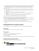
NOTE A fully populated PowerConnect B-DCX-4S weighs 103.50 kg (228.20 lb) with four FC8-48 port cards installed (192 ports) and requires a hydraulic or assisted lift to install it. 1. Unpack the PowerConnect B-DCX-4S. a. Cut the bands that encircle the packaging. b. Remove the lid and the kits and foam from the top of the chassis. c. Lift the cardboard box off the chassis and remove the plastic bag from around the chassis. Save the packing materials for use when returning the old chassis. d.
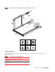
FIGURE 1 Port-Side Exhaust Kit assembly for 27 to 31 in. (68.58 to 78.74 cm) cabinets A I-3 I-2 I-4 I-5 B I-6 I-1 I-7 C Port Side (Exhaust) D E F 10-32 x .5" 10-32 x .63" 10-32 Clip Nut G H I 10-32 Retainer Nut Alignment Washer 6-32 x .25" Torque requirements Use the following torque settings when tightening screws that secure the rack mount kit and DCX-4S to the equipment cabinet. TABLE 2 Torque requirements for mounting screws Screw size Torque 6-32 x .25 in. (.
Install cabinet hardware 1. Determine how the DCX-4S can be oriented in the equipment cabinet so that the nonport side has access to intake air (cool). 2. Install clip nuts (F in Figure 1 on page 6) or retainer nuts (G in Figure 1 on page 6) in cabinet rail locations shown in Figure 2 on page 7. These nuts will secure the 10-32 screws that mount the Port Side Exhaust Kit shelf and DCX-4S to the cabinet. For rails with round holes, use clip nuts. For rails with square holes, use retainer nuts.
3. Install the shelf (C in Figure 1): a. The shelf can be adjusted to a length of between 27 and 31 inches (68.58 and 78.74 cm) to accommodate your cabinet size. To lengthen or shorten the shelf, loosen the four 6-32 screws in the four slots on the shelf (I-4 through I-7 in Figure 1 on page 6) and adjust the shelf to the desired length. Once adjusted, tighten the four 6-32 screws. b.
FIGURE 4 Installing air duct into side slot on shelf 5. Install the top-rail assembly (A in Figure 1 on page 6) to the air-duct assembly: Refer to Figure 5 on page 10. a. The top-rail assembly can be adjusted to a length of between 27 and 31 inches (68.58 to 78.74 cm) to fit on the inside of the cabinet rails. To lengthen or shorten the top-rail assembly, loosen the two 6-32 screws (I-3 in Figure 1 on page 6) and adjust the top-rail assembly to the desired length.
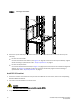
FIGURE 5 Securing top rail in cabinet. Install screws Install screws Install screws 6. Secure the top-rail assembly to the cabinet with four 10-32 screws, two screws on each end of the top-rail assembly. • For rails with round holes: Use two 10-32 screws with washers (E in Figure 1 on page 6) on each end of the top rail assembly. Tighten screws according to specifications under “Torque requirements” on page 6.
4. Carefully lift the DCX-4S and slide it into the cabinet. 5. Secure the DCX-4S to the cabinet with six 10-32 screws with washers. Tighten screws according to specifications under “Torque requirements” on page 6. NOTE Screws, clip nuts, and retainer nuts to secure the DCX-4S to the cabinet are provided in the DCX-4S hardware accessory kit. FIGURE 6 DCX-4S with 27 to 31 in. (68.58 to 78.
Installing with 18-24 in. (45.72 to 60.96 cm) kit Parts list The following parts list refers to items illustrated in Figure 7 on page 13. TABLE 3 Hardware for Port-Side Exhaust Kit for 18-in. to 24 in. (45.72 to 60.96 cm) cabinets Item Description Quantity A Top rail 1 B Top rail mounting brackets for 18-20 in., (45.72-50.8 cm) 20-22-in. (50.8-55.88 cm), and 22-24.in (55.88-60.96 cm) cabinets 3 C Duct 1 D Shelf 1 E Shelf saddle 1 F 10-32 x .5 in. (1.
FIGURE 7 Port-Side Exhaust Kit assembly for 18 to 24 in. (45.72 to 60.96 cm) cabinets B K-3 B B K-3 A K-3 K-2 C K-1 D Port Side (Exhaust) E F G H 10-32 x .5" 10-32 x .63" 10-32 Clip Nut I J K 10-32 Retainer Nut Alignment Washer 6-32 x .25" Torque requirements Use the following torque settings when tightening screws that secure the rack mount kit and DCX-4S to the equipment cabinet. TABLE 4 Torque requirements for mounting screws Screw size Torque 6-32 x .25 in. (.
Install cabinet hardware 1. Determine how the DCX-4S can be oriented in the equipment cabinet so that the nonport side has access to intake air (cool). 2. Install clip nuts (H in Figure 7 on page 13) or retainer nuts (I in Figure 7 on page 13) in cabinet rail locations shown in Figure 8 on page 14. These nuts will secure the 10-32 screws that mount the Port Side Exhaust Kit shelf and DCX-4S to the cabinet. For rails with round holes, use clip nuts. For rails with square holes, use retainer nuts.
3. Install the shelf saddle (E in Figure 7 on page 13) to the nonport side of the equipment cabinet .Install the saddle in the same vertical location as where the shelf installs on the port side of the rack. In using Figure 2 on page 7 as example, if the shelf is installed in location 23 on the port side, install the saddle in location 23 on the nonport side. Ensure that the words “THIS SIDE UP” on the saddle face towards the port side of the rack (refer to Figure 9).
FIGURE 10 Shelf installed in cabinet Install screws Port Side (Exhaust) Install screws NOTE For rails with round holes, use the clip nuts on the front rails for securing 10-32 screws. For rails with square holes, use the retainer nuts (H and I in Figure 7 on page 13). Also refer to Figure 8 on page 14. 5. Install the air-duct assembly (C in Figure 7 on page 13) by inserting it down into the side-slot on the shelf. Ensure that the tabs of the duct align and engage with the slots in the shelf.
FIGURE 11 Installing air duct into side slot on shelf 6. Install the top-rail inner bracket to the top-rail assembly: 7. a. Determine the size of the top-rail inner bracket that you will need to install on the top rail so that the top rail will fit on the inside of the equipment cabinet rails. Remove the appropriate bracket from the accessory kit. Note that the accessory kit contains three sizes, depending the depth of your equipment cabinet (B in Figure 7 on page 13). b.
Use the two standard 10-32 screws (F in Figure 7 on page 13) with blue Loctite on the threads and alignment washers (J in Figure 7 on page 13) on each end of the top rail assembly. Tighten screws according to specifications under “Torque requirements” on page 13. FIGURE 12 Securing top rail in cabinet. S Install DCX-4S in cabinet 1. Ensure that the door is removed from the port side of the DCX-4S. For instructions, refer to the corresponding DCX-4S Backbone Hardware Reference Manual. 2.
4. Carefully lift the DCX-4S and slide it into the cabinet. 5. Secure the DCX-4S to the cabinet with six 10-32 screws with washers, three screws on each side (Figure 13 on page 19). Tighten screws according to specifications under “Torque requirements” on page 13. NOTE Screws, clip nuts, and retainer nuts for securing the DCX-4S to the equipment rack are included in the DCX-4S hardware accessory kit. FIGURE 13 DCX-4S with 18 to 24 in. (45.72 to 60.
Port-Side Exhaust Kit Installation Procedure 53-1001802-01