
Users Guide
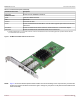
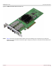
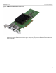
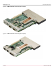
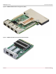
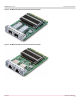
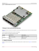
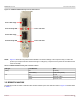
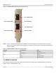
Table Of Contents
- Table of Contents
- 1 Regulatory and Safety Approvals
- 2 Functional Description
- 3 Network Link and Activity Indication
- 4 Features
- 4.1 Software and Hardware Features
- 4.2 Virtualization Features
- 4.3 VXLAN
- 4.4 NVGRE/GRE/IP-in-IP/Geneve
- 4.5 Stateless Offloads
- 4.6 Priority Flow Control
- 4.7 Virtualization Offload
- 4.8 SR-IOV
- 4.9 Network Partitioning (NPAR)
- 4.10 Security
- 4.11 RDMA over Converged Ethernet – RoCE
- 4.12 VMWare Enhanced Networking Stack (ENS)
- 4.13 Supported Combinations
- 4.14 Unsupported Combinations
- 5 Installing the Hardware
- 6 Software Packages and Installation
- 7 Updating the Firmware
- 8 Link Aggregation
- 9 System-Level Configuration
- 10 PXE Boot
- 11 SR-IOV – Configuration and Use Case Examples
- 12 NPAR – Configuration and Use Case Example
- 13 Tunneling Configuration Examples
- 14 RoCE – Configuration and Use Case Examples
- 15 DCBX – Data Center Bridging
- 16 DPDK – Configuration and Use Case Examples
- Revision History

Broadcom NetXtreme-E-UG304-2CS
20
NetXtreme-E User Guide User Guide for Dell Platforms
Figure 13: BCM957414AXXXX Activity and Link LED Locations
NOTE: Figure 13 shows the low-profile bracket installed. The surface markings of the component may not reflect the
product upon receipt. Broadcom reserves the right to change any component on the printed circuit board with the
same functionality.
3.3 BCM957416AXXXX
Each Ethernet interface has a link LED to indicate Link status and an activity LED to indicate data traffic. The LEDs are
shown in Figure 14 and described in Table 7.
Table 6: BCM957414AXXXX Activity and Link LED Locations
LED Type Color/Behavior Note
Activity Off No Activity
Green blinking Traffic Flowing Activity
Link Off No Link
Green Linked at 25 Gb/s
Yellow Linked at 10 Gb/s
Port 1 Link LED
Port 2 Link LED
Port 1 Activity LED
Port 2 Activity LED
Port 1 SFP28 Cage
Port 2 SFP28 Cage