
Administrator Guide

Fabric OS Administrator’s Guide 401
53-1002920-02
Traffic Isolation Zoning over FC routers with Virtual Fabrics
13
Traffic Isolation Zoning over FC routers with Virtual Fabrics
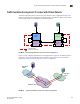
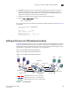
This section describes how you can set up TI zones over FC routers in logical fabrics. Figure 50
shows two physical chassis configured into logical switches. The initiator in FID 1 communicates
with the target in FID 3 over the EX_Ports in the base switches.
FIGURE 50 Example configuration for TI zones over FC routers in logical fabrics
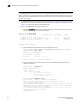
Figure 51 shows a logical representation of the configuration in Figure 50. This SAN is similar to
that shown in Figure 42 on page 387 and you would set up the TI zones in the same way as
described in “Traffic Isolation Zoning over FC routers” on page 386.
FIGURE 51 Logical representation of TI zones over FC routers in logical fabrics
= Dedicated Path
Base switch
Domain 1
LS3, FID1
Domain 3
Base switch
Domain 2
LS2, FID3
Domain 6
E
E
E EX
EXEX
E
F
EX
E
E
F
E E
= Ports in the TI zones
11
12
1
2
3
4
5
6
7
10
13
14
15
16
Backbone fabric
Edge fabric
Fabric 3
Edge fabric
Fabric 1
1
2
3
4
5
6
7
11
10
12
13
14
15
16
SW2
SW6
SW3
SW1