
Administrator Guide


24 Flow Vision Administrator’s Guide
53-1002999-01
Monitoring Fibre Channel routed fabrics
2
Monitoring FC router fabrics using proxy IDs
The following examples present flow definitions using deviceidmode set to PID mode.
flow --control -deviceidmode pid
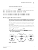
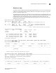
FIGURE 5 An FC router fabric
In Figure 5, the physical devices are A, B, and C. The proxy devices are Device A′, B′,
C′, A″, B″, and
C″, representing the physical devices A, B, and C, respectively. Figure 6 provides the PID, FID, and
proxy PID values for the following examples.
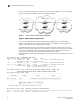
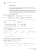
FIGURE 6 An FC router fabric annotated with PID, FID, and proxy PID values
NOTE
The proxy PID values for devices B″ and C″ were not generated for the following examples, they are
indicated by “xxxxxx” in Figure 6.
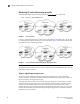
Edge-to-edge through an ingress port
To monitor a flow from Device A to Device B ingressing through EX_Port1, the source device
(srcdev) is Device A, the destination device (dstdev) is Device B
′, and the ingress port (ingrport) is
EX_Port1 (Traffic is running from left to right).
The following example creates a flow that filters frames passing from one edge fabric to another
edge fabric using a specific ingress port on the backbone. Notice that this is running in portwwn
mode rather than deviceid mode. The first two commands show the available ports and the
available FC routers. The third command creates a Flow Monitor flow named “e2e_src_dcx_wwn”
between device 220200 and device 01f001 ingressing through port 219, and the last command
displays the results of the flow.