
Deployment Guide

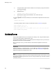


Using D,I notation, the port numbers for the TI zones in the logical fabric and base fabric are as
follows:
Port members for the TI zone in logical fabric Port members for the TI zone in base fabric
8,8 F_Port
8,1 E_Port
3,3 E_Port
3,10 E_Port
5,16 E_Port
5,8 E_Port
9,5 E_Port
9,9 F_Port
1,3 E_Port for ISL in logical switch
1,10 E_Port for XISL
7,12 E_Port for XISL
7,14 E_Port for XISL
2,16 E_Port for XISL
2,8 E_Port for ISL in logical switch
Notice that the base fabric zone contains a reference to port 1,3 even though the base switch with
domain 1 does not have a port 3 in the switch. This number refers to the port in the chassis with port
index 3, which actually belongs to LS3 in FID 1.
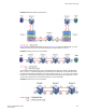
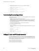
Traffic Isolation Zoning over FC routers with Virtual Fabrics
This section describes how you can set up TI zones over FC routers in logical fabrics. Figure 47
shows two physical chassis configured into logical switches. The initiator in FID 1 communicates with
the target in FID 3 over the EX_Ports in the base switches.
FIGURE 47 Example configuration for TI zones over FC routers in logical fabrics
Traffic Isolation Zoning over FC routers with Virtual Fabrics
362 Fabric OS Administrators Guide
53-1003130-01