
Deployment Guide


1. Select a logical switch from the Logical Switch list in the top-right corner of the Switch Explorer
window.
The selected switch displays in the Switch View . The icon on the Temp button indicates the overall
status of the temperature.
2. Click Temp on the Switch View .
The detailed temperature sensor states for the switch are displayed, as shown in Displaying switch
information on page 161.
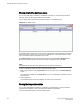
Viewing the power supply status
The icon on the Power button indicates the overall status of the power supply status. For more
information regarding switch power modules, refer to the appropriate hardware documentation.
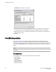
FIGURE 30 Power States window
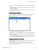
To view the power supply status, perform the following steps.
1. Select a logical switch from the Logical Switch list in the top-right corner of the Switch Explorer
window.
2. The selected switch displays in the Switch View. The icon on the Power button indicates the overall
status of the power supply.
3. Click Power on the Switch View. The detailed power supply states are displayed in the previous
figure. If you are using the Brocade 6510 or Brocade 6520, the Type column displays either AC or
DC. For all other hardware the value will be N/A.
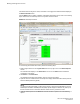
Checking the physical health of a switch
The Status button displays the operational state of the switch. The icon on the button displays the real-
time status of the switch.
If no data is available from a switch, the most recent background color remains displayed.
Any error-based status message that is based on a per-time interval cause the status to show faulty
until the entire sample interval has passed.
Viewing the power supply status
Web Tools Administrator's Guide 163
53-1003169-01