
Deployment Guide
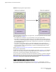

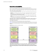

FID 8 are each connected to a non-Virtual Fabrics switch. The two logical switches and the non-Virtual
Fabrics switch are all in the same fabric, with FID 8.
FIGURE 24 Logical switches connected to other logical switches through physical ISLs
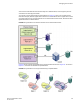
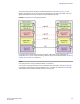
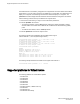
Figure 25 shows a logical representation of the configuration in Figure 24 .
FIGURE 25 Logical switches connected to form logical fabrics
The ISLs between the logical switches are dedicated ISLs because they carry traffic only for a single
logical fabric. In Figure 24 , Fabric 128 has two switches (the default logical switches), but they cannot
communicate with each other because they have no ISLs between them and they cannot use the ISLs
between the other logical switches.
NOTE
Only logical switches with the same FID can form a fabric. If you connect two logical switches with
different FIDs, the link between the switches segments.
Managing Virtual Fabrics
Fabric OS Administrators Guide 275
53-1003130-01