
Deployment Guide

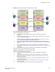
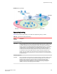
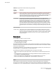

FIGURE 29 Example of logical fabrics in multiple chassis and XISLs
Use the following procedure to create a logical fabric using XISLs:
1. Set up the base switches in each chassis:
a) Connect to the physical chassis and log in using an account with the chassis-role
permission.
b) Enable the Virtual Fabrics feature, if it is not already enabled. See Enabling Virtual Fabrics
mode on page 285 for instructions.
Enabling Virtual Fabrics automatically creates the default logical switch, with FID 128. All
ports in the chassis are assigned to the default logical switch.
c) Create a base switch and assign it a fabric ID that will become the FID of the base fabric.
See Creating a logical switch or base switch on page 287 for instructions on creating a base
switch.
For the example shown in Figure 29 , you would create a base switch with fabric ID 8.
d) Assign ports to the base switch, as described in Adding and moving ports on a logical switch
on page 290.
e) Repeat step a through step d in all chassis that are to participate in the logical fabric.
2. Physically connect ports in the base switches to form XISLs.
3. Enable all of the base switches. This forms the base fabric.
4. Configure the logical switches in each chassis:
a) Connect to the physical chassis and log in using an account with the chassis-role
permission.
b) Create a logical switch and assign it a fabric ID for the logical fabric. This FID must be
different from the FID in the base fabric. See Creating a logical switch or base switch on
page 287 for instructions.
For the example shown in Figure 29 , you would create a logical switch with FID 1 and a
logical switch with FID 15.
c) Assign ports to the logical switch, as described in Adding and moving ports on a logical
switch on page 290.
d) Physically connect devices and ISLs to these ports on the logical switch.
Managing Virtual Fabrics
Fabric OS Administrators Guide 295
53-1003130-01