
Users Guide


76 53-1002998-01
Fabric Watch Administrator’s Guide
Switch monitoring
8
Brocade DCX 8510-8 default policy
The default Fabric Watch policy for the Brocade DCX 8510-8 with total power consumption of more
than 2,000 watts does not properly reflect the switch status on the power supply. Fabric Watch
users must manually update the default configuration for the minimum number of power supplies
to three if they have installed more than 256 ports in a DCX 8510-8 chassis.
NOTE
The presence of four or more FS8-18 encryption blades in the DCX Data Center Backbone causes
the Fabric Watch switch status policy for power supplies to assume a policy setting of 2,1.
Brocade 6505 default policy
The default Fabric Watch policy for the Brocade 6505 is one power supply in the left bay with an
optional configuration of two power supplies in both the left and right bays. The default
configuration for the Brocade 6505 is a 2 (DOWN) and 0 (MARGINAL), corresponding to a one
power supply configuration. If converting to a two power supply configuration, use the
switchStatusPolicySet command to manually change the configuration to 2,1 for the power supply
and fan FRU units. If converting back to a one power supply configuration, use the
switchStatusPolicySet command to manually change the power supply and fan FRU units to 1,0.
Implementing your switch status policy
After you plan and define your switch status policy, implement it using the following procedure.
1. Enter the switchStatusPolicySet command to configure each policy.
Each policy has two parameters that can be configured: Marginal and Down.
2. Set the number of units Marginal or Down based on your system requirements for each policy
or parameter.
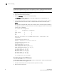
The following example shows a switch status policy for temperature:
Bad Temperatures contributing to DOWN status: (0..10) [0] 3
Bad Temperatures contributing to MARGINAL status: (0..10) [0] 1
The following example shows a switch status policy for fans:
Bad Fans contributing to DOWN status: (0..3) [0] 2
Bad Fans contributing to MARGINAL status: (0..3) [0] 1
Switch status policies are saved in a nonvolatile memory, and therefore are persistent until
changed.
Viewing your switch status policy
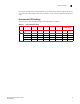
After you have defined and configured your switch status policy, view it with the
switchStatusPolicyShow command. The switchStatusPolicyShow command displays the following
policy parameters that determine the overall switch status:
NOTE
FCoE and VE_Ports are not considered in marginal port or faulty port calculations.
• Power Supplies—The power supply thresholds detect absent or failed power supplies.