53-1002576-02 December 2012 Brocade M6505 16 Gbps Fibre Channel SAN I/O Module Hardware Reference Manual ®
Copyright © 2012 Brocade Communications Systems, Inc. All Rights Reserved. Brocade, Brocade Assurance, the B-wing symbol, BigIron, DCX, Fabric OS, FastIron, MLX, NetIron, SAN Health, ServerIron, TurboIron, VCS, and VDX are registered trademarks, and AnyIO, Brocade One, CloudPlex, Effortless Networking, ICX, NET Health, OpenScript, and The Effortless Network are trademarks of Brocade Communications Systems, Inc., in the United States and/or in other countries.
Contents About This Document In this chapter . . . . . . . . . . . . . . . . . . . . . . . . . . . . . . . . . . . . . . . . . . . vii How this document is organized . . . . . . . . . . . . . . . . . . . . . . . . . . . . vii Document conventions . . . . . . . . . . . . . . . . . . . . . . . . . . . . . . . . . . . . viii Text formatting . . . . . . . . . . . . . . . . . . . . . . . . . . . . . . . . . . . . . . . viii Command syntax conventions . . . . . . . . . . . . . . . . . . . . . . . . . .
Chapter 2 Installing the SAN I/O Module Unpacking the SAN I/O Module . . . . . . . . . . . . . . . . . . . . . . . . . . . . . 11 Items included with the SAN I/O Module . . . . . . . . . . . . . . . . . . . . . 11 System reliability guidelines . . . . . . . . . . . . . . . . . . . . . . . . . . . . . . . . 12 Handling static-sensitive devices . . . . . . . . . . . . . . . . . . . . . . . . . . . . 12 Preparing the Blade Server Enclosure for the SAN I/O Module. . . .
Switch management . . . . . . . . . . . . . . . . . . . . . . . . . . . . . . . . . . . . . . 40 Viewing the configuration . . . . . . . . . . . . . . . . . . . . . . . . . . . . . . . . . . 40 Upgrading or downgrading firmware . . . . . . . . . . . . . . . . . . . . . . . . . 41 Changing the default account password . . . . . . . . . . . . . . . . . . . . . . 41 Changing the default account password at login . . . . . . . . . . . 42 Backing up the configuration . . . . . . . . . . . . . . . . . . . . . . .
vi Brocade M6505 16 Gbps Fibre Channel SAN I/O Module Hardware Reference Manual 53-1002576-02
About This Document In this chapter • How this document is organized . . . . . . . . . . . . . . . . . . . . . . . . . . . . . . . . . . vii • Document conventions . . . . . . . . . . . . . . . . . . . . . . . . . . . . . . . . . . . . . . . . . . viii • Notice to the reader . . . . . . . . . . . . . . . . . . . . . . . . . . . . . . . . . . . . . . . . . . . . . ix • Additional information . . . . . . . . . . . . . . . . . . . . . . . . . . . . . . . . . . . . . . . . . . . . x • Getting technical help .
Document conventions This section describes text formatting conventions and important notice formats used in this document.
Notes, cautions, and warnings The following notices and statements are used in this manual. They are listed below in order of increasing severity of potential hazards. NOTE A note provides a tip, guidance, or advice, emphasizes important information, or provides a reference to related information. ATTENTION An Attention statement indicates potential damage to hardware or data.
Corporation Referenced trademarks and products The Open Group UNIX VMware SUSE Linux Enterprise Server (SLES) XenServer XEN 6.0 Additional information This section lists additional Brocade and industry-specific documentation that you might find helpful. Brocade resources To get up-to-the-minute information, go to http://my.brocade.com to register at no cost for a user ID and password. White papers, online demonstrations, and data sheets are available through the Brocade web site at: http://www.
• • • • • • • • • Fabric OS MIB Reference Fabric OS Message Reference Access Gateway Administrator’s Guide SAN TECH NOTE - Preparing to Install the Brocade Access Gateway Web Tools Administrator’s Guide Fabric Watch Administrator’s Guide Brocade M6505 16 Gbps Fibre Channel SAN I/O Module QuickStart Guide Release notes for the Fabric OS version running on the SAN I/O Module Release notes specific to the SAN I/O Module NOTE Refer to the latest documentation version for the most up-to-date product informatio
Document feedback Quality is our first concern at Brocade and we have made every effort to ensure the accuracy and completeness of this document. However, if you find an error or an omission, or you think that a topic needs further development, we want to hear from you. Forward your feedback to: documentation@brocade.com Provide the title and version number of the document, and as much detail as possible about your comment, including the topic heading and page number and your suggestions for improvement.
Chapter Brocade M6505 Product Overview 1 In this chapter • SAN I/O Module overview . . . . . . . . . . . . . . . . . . . . . . . . . . . . . . . . . . . . . . . . . 1 • Operating system support. . . . . . . . . . . . . . . . . . . . . . . . . . . . . . . . . . . . . . . . . 2 • Hardware features and functionality . . . . . . . . . . . . . . . . . . . . . . . . . . . . . . . . 2 • Software features . . . . . . . . . . . . . . . . . . . . . . . . . . . . . . . . . . . . . . . . . . . . . . .
1 Operating system support Operating system support Brocade Fabric OS has no specific host operating system (OS) dependencies. The Fabric OS in the switches allows for any Fibre Channel-compliant device to attach to switches as long as it conforms to the standards for device login, name service, and related Fibre Channel features. The operating systems listed in Table 1 are for the host machine running Brocade management applications outside the Fabric OS, such as Brocade Network Advisor (BNA).
Software features 1 Software features The Brocade M6505 16 Gbps Fibre Channel SAN I/O Module supports the following software features. For updates to the supported feature set, refer to the Brocade Fabric OS Administrator’s Guide and product release notes for additional information. • Access Gateway (AG) mode and Native Fabric mode. (Refer to “Access Gateway and Native Fabric modes” on page 5.) The SAN I/O Module ships in Access Gateway mode, but it can support the standard Native Fabric (Switch) mode.
1 Ports on Demand • SNMP/MIB monitoring functionality contained within the Ethernet Control MIB-II (RFC1213-MIB) • • • • NTP client support (NTP V3) • • • • Switch banner support FTP support for firmware upgrades End-to-end optics and link validation Registered State Change Notification (RSCN), which notifies a device of a change within the fabric Syslog remote logging capabilities RASlogs to indicate invalid traffic isolation zones Four RMON groups: history, statistics, alarms, and events Optional
ISL trunking groups 1 ISL trunking groups If your SAN I/O Module has an optional Brocade ISL Trunking license, external ports can form trunking groups of ISLs between adjacent switches. ISL Trunking optimizes the performance and availability of SAN fabrics while simplifying ISL management. All external ports (0, 17 through 23) can be formed into a single 8-port trunk, or any combination of 2- to 7-port trunk. For details about Brocade ISL Trunking, refer to the Fabric OS Administrator’s Guide.
1 Optional Brocade licenses Native Fabric mode Native Fabric mode can be accessed by disabling the default AG mode. Once the SAN I/O Module is in Native Fabric mode, it provides support for the following: • Up to 8 external auto-sensing and auto-negotiating (4, 8, or 16 Gbps) Fibre Channel ports.
Hardware description 1 Hardware description This section describes the Brocade M6505 16 Gbps Fibre Channel SAN I/O Module as shipped from the factory. For specifications, such as installed memory, weight and physical dimensions, facility requirements, and architectural specifications, refer to Appendix A, “SAN I/O Module Specifications”. SAN I/O Module front panel All external ports and LEDs are accessible from the front panel of the Brocade M6505 16 Gbps Fibre Channel SAN I/O Module.
1 Hardware description 1 2 6 3 5 4 1 Ports with port status LEDs 4 Power status LED 2 RJ-45 console port 5 Server management status/indicator LED 3 SAN I/O Module status LED 6 SAN I/O Module release lever FIGURE 1 Brocade M6505 16 Gbps Fibre Channel SAN I/O Module front panel For more information on SAN I/O Module front panel LEDs, refer to “Interpreting SAN I/O Module LED activity” on page 35.
Hardware description 1 SAN I/O Module side view The SAN I/O Module connects to the I/O module bay of the Dell M1000e Blade Server Enclosure by way of the backplane connectors. (Refer to Figures 2.) The SAN I/O Module seats correctly when the release lever is closed securely. Once the SAN I/O Module is securely seated, the backplane connectors become active, allowing the SAN I/O Module to be configured in the Dell M1000e Blade Server Enclosure.
1 SFP+ transceivers SFP+ transceivers The SAN I/O Module is designed to work exclusively with Brocade-branded small form-factor pluggable plus (SFP+) optical transceivers. The SFP+ transceivers are hot-swappable, thus allowing for connection to external devices without removing the SAN I/O Module from the Dell M1000e Blade Server Enclosure. For information on inserting or removing SFP+ transceivers, refer to “Removing and replacing SAN I/O Modules” on page 37.
Chapter 2 Installing the SAN I/O Module In this chapter • Unpacking the SAN I/O Module . . . . . . . . . . . . . . . . . . . . . . . . . . . . . . . . . . . • Items included with the SAN I/O Module. . . . . . . . . . . . . . . . . . . . . . . . . . . . • System reliability guidelines . . . . . . . . . . . . . . . . . . . . . . . . . . . . . . . . . . . . . . • Handling static-sensitive devices . . . . . . . . . . . . . . . . . . . . . . . . . . . . . . . . . .
2 System reliability guidelines System reliability guidelines To help ensure proper cooling, performance, and system reliability, make sure the following requirements are met: • Each of the I/O module bays at the rear of the Dell M1000e Blade Server Enclosure contains either a SAN I/O Module or a filler panel. • A removed hot-swappable SAN I/O Module is replaced with an identical SAN I/O Module or filler panel within 60 seconds of removal.
Inserting the SAN I/O Module in the Blade Server Enclosure 2 • Any protective cover on the SAN I/O Module backside connector is removed. • If you are replacing an existing SAN I/O Module with a new module, the new SAN I/O Module should be ready to be inserted within 60 seconds from the removal of the old module to maintain the proper cooling level in the chassis.
2 Inserting the SAN I/O Module in the Blade Server Enclosure 4. Ensure that the release lever is fully extended so the SAN I/O Module can be seated properly in the Dell M1000e Blade Server Enclosure, as shown in Figure 4. 1 2 1 Release latch FIGURE 4 2 Release lever SAN I/O Module latching mechanism (open position) 5. With the port side facing you and the release lever fully extended, slide the SAN I/O Module in the Dell M1000e Blade Server Enclosure I/O module bay. 6.
Handling SFP+ transceivers 2 Handling SFP+ transceivers Before installing an SFP+ transceiver, be aware of the following: • The housing on the SFP+ transceiver includes an integral guide key that is designed to prevent you from inserting the transceiver incorrectly. • Use minimal pressure when you insert an SFP+ transceiver in the port. Forcing the transceiver into the port can cause damage to the transceiver or the SAN I/O Module port.
2 Cabling guidelines 1. Review the section “Handling SFP+ transceivers” on page 15. 2. If your SAN I/O Module ships with insert plugs in the unused external ports, remove the insert plugs from the ports to be used. 3. Insert the SFP+ transceiver into a port until it is firmly seated and the latching mechanism clicks. NOTE SFP+ Transceivers are keyed to ensure correct orientation. If an SFP+ transceiver does not install easily, ensure that it is correctly oriented. 4.
Data transmission ranges 2 Data transmission ranges Table 4 provides the data transmission ranges for the transceivers, port speeds, and cable types. TABLE 4 Supported optical tranceivers, speeds, cables, and distances Transceiver type Form factor Link Speed1 Multi-node media (50 microns) (OM1) Multi-mode media (50 microns) (OM2) Multi-mode media (50 microns) (OM3) Multi-mode media (50 microns) (OM4) Single-mode media SWL SFP+ 2 Gbps 150 m (492 ft.) 300 m (984 ft.) 500 m (1640 ft.
2 18 Data transmission ranges Brocade M6505 16 Gbps Fibre Channel SAN I/O Module Hardware Reference Manual 53-1002576-02
Chapter 3 Configuring the SAN I/O Module In this chapter • Items required . . . . . . . . . . . . . . . . . . . . . . . . . . . . . . . . . . . . . . . . . . . . . . . . . • Modifying the SAN I/O Module IP address . . . . . . . . . . . . . . . . . . . . . . . . . . • Connecting to the SAN I/O Module using Web Tools . . . . . . . . . . . . . . . . . . • Connecting the SAN I/O Module to the Ethernet network . . . . . . . . . . . . . . • Connecting the SAN I/O Module to the fabric . . . . . . . . . . . . .
3 Modifying the SAN I/O Module IP address • Access to the following publications: - Dell PowerEdge M1000e Enclosure Owner’s Manual - Dell Chassis Management Controller Firmware Version 4.
Modifying the SAN I/O Module IP address FIGURE 5 3 CMC Setup tab Refer to the Dell PowerEdge M1000e Enclosure Owner’s Manual that comes with your Dell M1000e Blade Server Enclosure for more information. Using the CMC CLI to set the IP address To modify the SAN I/O Module IP address through the Chassis Management Controller (CMC) CLI, perform the following steps: 1. Establish a Telnet session to the CMC CLI. 2.
3 Modifying the SAN I/O Module IP address Fibre Channel IP Addresss [none]: Fibre Channel Subnetmask [none]: Gateway IP Address [0.0.0.0]:10.32.48.1 DHCP [Off]: IP address is being changed...Done. 7. Enter ipAddrShow to verify the IP address was correctly set. switch:admin> ipaddrshow Ethernet IP Address: 10.32.53.47 Ethernet Subnetmask: 255.255.240.0 Fibre Channel IP Addresss: none Fibre Channel Subnetmask: none Gateway IP Address 10.32.48.
Modifying the SAN I/O Module IP address e. f. 3 From the COM Port Properties window, select the following configuration values. Bits per second 9600 Databits 8 Parity None Stop bits 1 Flow control None Log in using the default administrative account: Login: admin Password: password g. When prompted, either change the administrative password, or press Ctrl-C to bypass. For LINUX or UNIX a. Enter the following command at the command prompt: tip /dev/ttyb -9600 b.
3 Connecting the SAN I/O Module to the Ethernet network 4. Enter ipAddrShow at the prompt to verify that the address was set correctly. switch:admin> ipaddrshow Ethernet IP Address: 10.32.53.47 Ethernet Subnetmask: 255.255.240.0 Fibre Channel IP Addresss: none Fibre Channel Subnetmask: none Gateway IP Address 10.32.48.
Connecting the SAN I/O Module to the fabric 3 If you are in AG mode and want to change to Native Fabric mode before connecting the SAN I/O Module to the fabric, refer to “Changing from Access Gateway mode to Native Fabric mode” on page 31. 1. If the Brocade M6505 16 Gbps Fibre Channel SAN I/O Module is in Native Fabric mode, continue to step 2 and step 3. If the Module is in Access Gateway mode, go on to step 4. 2. Log in to the SAN I/O Module through a Telnet connection using the admin account. 3.
3 Connecting the SAN I/O Module to the fabric System (yes, y, no, n): [no] WARNING: The domain ID will be changed. The port level zoning may be affected. c. Re-enable the SAN I/O Module by entering the switchEnable command. NOTE It can take up to 20 seconds for the newly added SAN I/O Module to appear in the fabric display with its newly assigned domain ID. 4. If you must install SFP+ transceivers, install them in the external Fibre Channel ports, as required. a.
Connecting the SAN I/O Module to the fabric 3 9. Back up the SAN I/O Module configuration to an FTP server by typing the configUpload command and following the prompts. This command uploads the SAN I/O Module configuration to the server, making it available for downloading to a replacement SAN I/O Module if necessary. Brocade recommends backing up the configuration on a regular basis to ensure that a complete configuration is available for downloading to a replacement SAN I/O Module.
3 28 Connecting the SAN I/O Module to the fabric Brocade M6505 16 Gbps Fibre Channel SAN I/O Module Hardware Reference Manual 53-1002576-02
Chapter 4 Operating the SAN I/O Module In this chapter • Interoperability. . . . . . . . . . . . . . . . . . . . . . . . . . . . . . . . . . . . . . . . . . . . . . . . . • Activating Ports on Demand . . . . . . . . . . . . . . . . . . . . . . . . . . . . . . . . . . . . . . • Changing from Native Fabric mode to Access Gateway mode . . . . . . . . . . . • Changing from Access Gateway mode to Native Fabric mode . . . . . . . . . . . • Access Gateway mode default port mapping . . . . . . . . . . . . . . .
4 Activating Ports on Demand TABLE 5 Interoperability (Continued) Feature/Function Description Trunking Supported only between two Brocade switches.
Changing from Access Gateway mode to Native Fabric mode 4 For new SAN I/O Module installations, perform the following procedure before connecting to an existing SAN. ATTENTION Do not use this method if the SAN I/O Module is operating in an existing SAN because traffic will be disrupted. 1. Disable the SAN I/O Module. NOTE If Secure Fabric OS is enabled, you cannot use Telnet or SSH to disable the SAN I/O Module. For details about using Web Tools, refer to the Brocade Web Tools Administrator’s Guide.
4 Changing from Access Gateway mode to Native Fabric mode Disabling Access Gateway mode To disable AG mode on the SAN I/O Module, perform the following procedure. 1. Before disabling a switch in AG mode, save the current configuration file using the configUpload command in case you need this configuration again. 2. Enter the switchDisable command. switch:admin> switchdisable This command disables all user ports on a switch. All Fibre Channel ports are taken offline.
Changing from Native Fabric mode to Access Gateway mode 4 Changing from Native Fabric mode to Access Gateway mode Converting to Access Gateway (AG) mode allows you to use the module as a device management tool that transparently connects hosts to the fabric. Refer to the Brocade Access Gateway Administrator’s Guide for information on changing from Native Fabric mode to AG mode. Access Gateway mode default port mapping The SAN I/O Module can contain 24 total ports.
4 Interpreting POST results Interpreting POST results The power-on self-test (POST) system check is performed each time the SAN I/O Module is powered on, rebooted, or reset.
Interpreting SAN I/O Module LED activity 4 Interpreting SAN I/O Module LED activity The SAN I/O Module uses LEDs to indicate status, as shown in Figure 6. 1 2 3 4 1 FC external port status 3 SAN I/O Module power status 2 SAN I/O Module status 4 Server management status/indicator FIGURE 6 SAN I/O Module front panel LEDs LEDs are used to indicate switch health, status of the external ports, and power to the SAN I/O Module. LEDs are also used to indicate diagnostics and test results.
4 Interpreting SAN I/O Module LED activity Power-on self-test LEDs The SAN I/O Module LEDs flash in various patterns during bootup, power-on self-test (POST), or other diagnostic tests. This is normal and does not indicate a problem unless the LEDs do not indicate a healthy state after all boot processes and diagnostic tests are complete. • If POST fails, LEDs appear yellow. • If POST is successful, LEDs appear green. NOTE The SAN I/O Module will continue to operate after POST indicates a fatal error.
Removing and replacing SAN I/O Modules TABLE 7 4 Interpreting front panel LEDs during normal operation (Continued) SAN I/O Module status LED SAN I/O Module power LED Server management LED Off (no light) SAN I/O Module is off or power supplies for the Blade Server or onboard DCC have failed Steady green No errors and all ports are ready for use Steady amber Boot-up state, port(s) offline, or in reset state Blinking (green or amber) One or more environmental ranges are exceeded, or error log con
4 Removing and replacing SAN I/O Modules For added convenience, you can refer to Figure 7, which provides the generic process for removing an SFP+ transceiver from a port. Cable Release Bale SFP 1 3 SFP 2 4 1 Cable release clip 3 Opening the bale on the SFP+ 2 Disconnecting the cable 4 Removing the SFP+ FIGURE 7 Removing an SFP+ transceiver from a port 4. Disconnect the RJ-45 Ethernet cable from the COM serial port. 5. Press the release latch to free the release lever.
Removing and replacing SFP+ transceivers and cables 4 10. Reconnect the cables that you disconnected in step 3. For additional information about connecting cables, refer to “Installation and safety guidelines when handling cables” on page 16, and the documentation that comes with the SFP+ transceivers to which the cables have been connected. 11. (Optional) Reconnect the RJ-45 Ethernet cable that you disconnected in step 4. 12.
4 Switch management Switch management You can access the SAN I/O Module from either the Dell M1000e Blade Server Enclosure Chassis Management Controller (CMC), or directly from the SAN I/O Module. Managing the SAN I/O Module can be performed using Web Tools, through Brocade Network Advisor (BNA) management software, which offers a holistic view of the SAN, or through the CLI, which is accessible using Telnet/SSH, or the local RJ-45 serial port.
Upgrading or downgrading firmware 4 fcRoute.port.8.portMode:0 fcRoute.port.8.autoElp:7 fcRoute.port.9.xportAdmin:DISABLED fcRoute.port.9.fabricId:5 fcRoute.port.9.ratov:10000 fcRoute.port.9.edtov:2000 fcRoute.port.9.frontConfigDid:160 fcRoute.port.9.portType:400 fcRoute.port.9.portMode:0 fcRoute.port.9.autoElp:7 fcRouteParam.port.8.rportCost:0 fcRouteParam.port.9.rportCost:0 fcRoute.xlate.persistxdState:1 fcRouteParam.lsan.
4 Backing up the configuration Changing the default account password at login 1. Connect to the SAN I/O Module and log in using the default administrative account. 2. At each of the “Enter new password” prompts, enter a new password. User-defined passwords can have from 8 through 40 characters. They must begin with an alphabetic character and can include numeric characters, the period (.), and the underscore ( _ ). Passwords are case-sensitive. A sample output of changing passwords is provided.
Locating the serial number information 4 Locating the serial number information Before contacting service support, be sure to obtain the SAN I/O Module serial number. NOTE When contacting service support, you will also need the Dell service tag. The service tag label is located on the outside of SAN I/O Module; however, the label is not visible when the SAN I/O Module is inserted in the Dell M1000e Blade Server Enclosure. You can access the service tag number using cli commands.
4 44 Locating the serial number information Brocade M6505 16 Gbps Fibre Channel SAN I/O Module Hardware Reference Manual 53-1002576-02
Appendix A SAN I/O Module Specifications In this appendix • Processor and memory specifications . . . . . . . . . . . . . . . . . . . . . . . . . . . . . . • Weight and physical dimensions . . . . . . . . . . . . . . . . . . . . . . . . . . . . . . . . . . • Environmental specifications . . . . . . . . . . . . . . . . . . . . . . . . . . . . . . . . . . . . . • Electrical specifications . . . . . . . . . . . . . . . . . . . . . . . . . . . . . . . . . . . . . . . . . • Architectural specifications. . . .
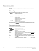
A Environmental specifications Environmental specifications Table 10 lists the environmental specifications for the SAN I/O Module. TABLE 10 Environmental specifications Condition Operating Non-operating Temperature 0°C to 40°C (32°F to 104°F) -20°C to 70°C (-4°F to 158°F) Humidity 10% to 90%, non-condensing at 29°C (84.2°F) 5% to 95%, non-condensing at 38°C (100.
Supported HBAs TABLE 12 A Architectural specifications (Continued) Feature Description Port types Fabric OS Native mode • E_Port (expansion port) • F_Port (fabric-enabled port) • U_Port (self-discovery based on switch type) AG mode • F_Port (fabric-enabled port) • N_Port (NPIV-enabled port) Fabric services (Native Fabric mode only) Simple Name Server, Registered State Change Notification (RSCN) Supported HBAs For information regarding supported Fibre Channel mezzanine adapters, refer to Dell-speci
A Regulatory compliance BSMI statement (Taiwan) KC statement (Republic of Korea) VCCI statement (Japan) This is a Class A product based on the standard of the Voluntary Control Council for Interference by Information Technology Equipment (VCCI). If this equipment is used in a domestic environment, radio disturbance might arise. When such trouble occurs, the user might be required to take corrective actions. CE statement ATTENTION This is a Class A product.
Regulatory compliance A Canadian requirements This Class A digital apparatus meets all requirements of the Canadian Interference-Causing Equipment Regulations, ICES-003 Class A. Laser compliance This equipment contains Class 1 laser products and complies with FDA Radiation Performance Standards, 21 CFR Subchapter I and the international laser safety standard EN60825-1:1994 +A1+A2. CAUTION Use only optical transceivers that are qualified by Brocade Communications Systems, Inc.
A Environmental regulation compliance Environmental regulation compliance This section describes the China ROHS environmental regulatory compliance requirements for the SAN I/O Module. Environmental Protection Use Period (EPUP) Disclaimer In no event do the EPUP logos shown on the product and field-replaceable units (FRUs) alter or expand that warranty that Brocade provides with respect to its products as set forth in the applicable contract between Brocade and its customer.
A Environmental regulation compliance China ROHS Hazardous Substances/Toxic Substances (HS/TS) Concentration Chart Name of the Component Hazardous/Toxic Substance/Elements Lead (PB) Mercury (Hg) Cadium (CD) Hexavalent Chromium (CR6+) Polybrominated Biphenyl (PBB) Polybrominated Diphenyl Ether (PBDE) Fibre Channel Switch X O O O O O PCBA cards X O O O O O SFPs (optical cable connectors) X O O O O O Sheet Metal X O O O O O Mechanical brackets and Slides X O O O O O
A 52 Environmental regulation compliance Brocade M6505 16 Gbps Fibre Channel SAN I/O Module Hardware Reference Manual 53-1002576-02
Index A C access gateway enhancements, 3 storage arrays, 5 access gateway mode, 1, 3, 5 default port mapping, 33 Adaptive Networking license, 6 Advanced Performance Monitoring enhancements, 30 license, 6 ag --modeShow command, 32 ag --modeDisable command, 32 architectural specifications, 46 ASIC, 6 Australia regulatory compliance, 50 cables caution, 16, 39 guidelines, 16 part numbers, 17 radius, 16 Canada regulatory compliance, 49 Canadian requirements, 49 caution indicator, ix CE statement, 48 chassisS
Index D G diagnostics, 16 LED operation, 36 dimensions, 45 DPOD (see dynamic ports on demand) dynamic ports on demand, 3, 4 licensing, 4 guidelines reliability, 12 static-sensitive devices, 12 E electrostatic discharge, 11 enhanced group management, 3 enterprise model, 11 EPUP disclaimer, 50 errShow command, 34 ESD, 11 Ethernet connection, 14 European Union regulatory compliance, 50 external ports, 1 F Fabric OS, 2, 33 native mode, 5 release notes, x fabric OS, 3 fabric OS native mode changing from ac
Index K N KC statement (Republic of Korea), 48 Korea regulatory compliance, 50 native fabric mode, 1 port types, 6 New Zealand regulatory complaince, 50 NPIV, 1, 5 NTP client support, 4 L laser compliance, 49 LED, 34, 35 LED activity interpreting, 35 LEDs ACT led, 36 diagnostics, 36 LINK led, 36 management health status, 2 normal operation, 36 port and port status, 8 POST, 36 power status, 8 server management status, 8 switch status, 2, 8 system power, 2 licenseIdShow command, xi licenses Adaptive Netw
Index ports on demand dynamic, 4 POST, 16, 34 LEDs bootup, 36 results, 35 R RBAC, 3 RCSN, 29 regulatory compliance, 47 Australia, 50 BSMI statement (Taiwan), 48 Canada, 49 Canadian requirements, 49 CE statement, 48 environmental, 50 European Union, 50 FCC warning (US only), 47 Japan, 50 KC statement (Republic of Korea), 48 Korea, 50 laser compliance, 49 New Zealand, 50 RTC battery, 49 United States, 49 VCCI staetment (Japan), 48 release latch, 13 locking, 14 operating, 14 release lever, 7, 13, 14 operatin
Index T Telnet, 42 terminal session with I/O module, 22 toxic substances, 51 transceivers (see also optical transceivers), 10 translative mode, 29 trunking, 30 U United States regulatory compliance, 49 V VCCI statement, 48 W warning indicator, ix web browser, 24 Web Tools, 24 Java, 24 using to connect SAN I/O Module, 24 weight, 45 wwn command, xi Z zoning, 3, 6, 33 Brocade M6505 16/8 Gbps Fibre Channel SAN I/O Module Hardware User’s Guide 53-1002576-02 57
Index 58 Brocade M6505 16/8 Gbps Fibre Channel SAN I/O Module Hardware User’s Guide 53-1002576-02