
Administrator Guide


C1048P Back Panel
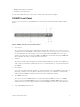
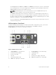
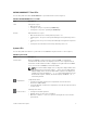
The back panel of the C1048P PE is shown in the following illustration and described below.
Figure 3. C1048P Back Panel
1. Stack ports: Each C1048P has two fixed mini-SAS (STD) stacking connectors on its back panel. Stack
port 1 is on top; stack port 2 is on the bottom.
You can stack up to eight C1048P PEs using the mini-SAS ports on the back panel. A C1048P PE
supports stacking only with other C1048P PEs. When you connect multiple C1048P PEs using the
stack ports, the PEs operate as a single unit with up to 384 front panel ports. The stack operates and
is managed from a C9010 switch as a single entity.
In a C1048P stack, the Stack Master/Member LED on the front panel indicates operational status
(standalone, stack master, or member unit). For more information about C1048P LED behavior, see
System LEDs.
2. Stack port 1: Activity LED
3. Stack port 1: Link LED
4. Main AC power supply connector: The C1048P PE has an internal 1000-watt power supply that
feeds up to 24 PoE devices at full PoE+ power (850W). PoE power is dynamically allocated.
NOTE: The AC power connector on a C1048P requires an IEC-320-C15 power cable, which is
different than the C13 power cable used on most lower wattage switches.
5. External DC power supply connector: You can connect an additional external power supply
(MPS1000) to provide 1000 watts and full power coverage for all 48 PoE devices (1800W).
6. Fan vents: Two fans are used to cool the C1048P PE.
7. Stack port 2: Activity LED
8. Stack port 2: Link LED
C1048P Hardware Description
9