Dell Networking C1048P Getting Started Guide Regulatory Model: C1048P
Notes, Cautions, and Warnings NOTE: A NOTE indicates important information that helps you make better use of your computer. CAUTION: A CAUTION indicates either potential damage to hardware or loss of data and tells you how to avoid the problem. WARNING: A WARNING indicates a potential for property damage, personal injury, or death. Copyright © 2015 Dell Inc. All rights reserved. This product is protected by U.S. and international copyright and intellectual property laws.
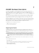
1 About This Guide This document is intended to help you get started by installing the C1048P port extender (PE) for use with a C9010 switch and connecting to a network. For more detailed information about C1048P installation and software configuration, see the documents in the following table, which are available on the Dell Networking Support website (Dell Networking Support). Table 1.
2 C1048P Hardware Description The Dell Networking C1048P is a stackable Gigabit Ethernet port extender (PE) for campus access deployments. The C1048P is used as a 1 rack unit (RU) port extender for the C9010 modular chassis and requires a C9010 switch to operate. The C1048P functions as a remote line card that is physically connected to, and provisioned by, a C9010 over 10GbE uplinks. You can connect up to 40 C1048P PEs to a C9010 switch.
• Warranty and Support Information • Software License Agreement You can order additional items, such as optics, cables, and external power supplies. C1048P Front Panel The ports on the front panel of the C1048P PE are shown in the following illustration and described below. Figure 1. C1048P Front Panel: Ports and Reset Button 1. Console port The console port provides serial communication using the RS-232 protocol to connect a console terminal and access the C1048P command-line interface (CLI).
The 48 Gigabit Ethernet (10BASE-T, 100BASE-TX, 1000BASE-T) RJ-45 ports connect to downstream servers and edge devices. These ports support auto-negotiation for speed, flow control, and duplex transmission. C1048P Gigabit Ethernet ports are numbered 1 to 48. NOTE: Dell Networking does not recommend that you connect a Gigabit Ethernet port to another switch or bridge. A loop in the topology may result.
10/100/1000BASE-T Port LEDs The following table describes 10/100/1000BASE-T port LEDs (items 1 and 2 in Figure 2). C1048P 10/100/1000BASE-T Port LEDs LED Description Link Link speed on port • • • Activity Off: No link is up. Solid green: The port is operating at 1000 Mbps. Solid yellow: The port is operating at 10/100 Mbps. Data transmission on port • • • • Off: No transmit/receive activity and PoE power is off. Flashing green: The port is actively transmitting/receiving and PoE power is off.
LED Description • Off: Error condition — There is no power reaching the PE or the PE has a power failure. System operational status Status Fan • • • • Solid green: Normal operation Blinking green: The PE is booting. Solid red: Critical system error Blinking red: Non-critical system error, such as a fan or power supply failure • • Solid green: The fan is powered on and is operating at normal RPM speed.
C1048P Back Panel The back panel of the C1048P PE is shown in the following illustration and described below. Figure 3. C1048P Back Panel 1. Stack ports: Each C1048P has two fixed mini-SAS (STD) stacking connectors on its back panel. Stack port 1 is on top; stack port 2 is on the bottom. You can stack up to eight C1048P PEs using the mini-SAS ports on the back panel. A C1048P PE supports stacking only with other C1048P PEs.
Stack Port LEDs The stack port LEDs are located to the right of each stack port. The Link LED is above the Activity LED. Figure 4. C1048P Back Panel: Stack Port LEDs 1. Stack port 1: Activity LED 2. Stack port 1: Link LED 3. Stack port 2: Activity LED 4. Stack port 2: Link LED Table 2. C1048P Stack Port LEDs Stack Port LED Description LNK Stack port link • • ACT Off: No link is up. Solid green: Stack link is up. Stack port activity • • Off: No data link activity.
other devices that might damage the cables. If necessary, allow one RU space between devices to provide room for cabling. • Temperature: The ambient temperature around the operating PE is from 0 to 45°C (32 to 113°F). • Altitude: Altitude at the installation site is below 10,000 feet (3048 m). • Humidity: The relative humidity around the operating PE is 8% to 85% (non-condensing) with a maximum humidity gradation of 10% per hour.
3 Installing the Hardware To install the C1048P PE, mount it into a 19" wide, EIA-310-E compliant rack. You can install the C1048P in a 1U 4-post front-rack or 1U 2-post (flush and center) rack configuration. Using a rack mount tray is optional. To install the C1048P PE in a rack: 1. (Optional) Install a rack mount tray in a 2- or 4-post rack. 2. Install the C1048P chassis in the rack using mounting brackets. 3. Connect the C1048P to a C9010 switch. 4.
• Reduced air flow — Install the port extender in the rack so that the front-to-back airflow (I/O ports to PSU) is not obstructed. • Reliable earthing — Maintain reliable earthing of rack-mounted equipment. Pay particular attention to supply connections other than direct connections to the branch circuit; for example, use of power strips. • Rack mounting — Do not mount the port extender with the rear panel facing in the downward position.
Installing the C1048P in a Rack You can install the C1048P in a 1 RU 4-post front-rack or 1 RU 2-post (flush and center) rack configuration. Although the procedure in this section describes C1048P installation in a 1 RU 2-post front-rack configuration, follow the same steps to install a C1048P in a 1 RU 4-post rack. WARNING: Never mount the C1048P in a rack that is suspended under a table or desk, or attached to a wall.
5. Secure the C1048P to the rack using the rack bolts (provided with the mount brackets) or cage nuts and cage-nut bolts with washers (provided with the rack). Tighten the bolts on the bottom of each bracket flange first; then tighten the bolts on top (item 1 in Figure 7). CAUTION: Make sure that the rack bolts provided with the mounting brackets fit the threaded holes in the rack. Figure 7.
3. Connect one end of an appropriately connectorized fiber-optic cable into the port. Connect the other end to an SFP+ connector in a C9010 switch. Stacking Multiple C1048P Port Extenders The C1048P supports PE stacking, which allows multiple C1048P units to act as a single port extender. You can stack up to eight C1048Ps using the stack ports on the back panel. C1048P stack ports support the Serial Attached SCSI (SAS) protocol and operate as mini-SAS ports.
Figure 8. C1048P Stack in a Ring Topology 1. C1048P stack 2. Mini-SAS cables attached in a ring topology The C1048P stack in Figure 8 is connected in a ring topology with the following physical connections between port extenders. The PEs are numbered Unit 0 to Unit 2. After you power on the stack units, the Stack Master LED on the C1048P that is elected master displays solid green. • The bottom mini-SAS port on the top unit is connected to the top mini-SAS port on the middle unit.
The C1048P has one internal power supply. The AC and DC power connectors are on the back panel (see Back Panel). To power up a C1048P, connect it to an AC power source: 1. Using an IEC-320-C15 power cable with safety ground, connect the power cable to the AC main receptacle on the back panel. 2. Connect the power cable to a grounded AC outlet. If you connect to a redundant, external DC power supply, use the Dell Networking MPS1000.
Configuring the Software 4 To complete the hardware installation, install the C1048P in a rack, attach an uplink cable to a parent C9010 switch, (optionally) set up a C1048P stack, and power on the port extender. To provision a C1048P, you can configure basic software settings from the C9010 console either before or after you connect the C1048P to a C9010. For example, you can pre-configure software settings to download from the parent C9010 after you power on the C1048P.
command. The cascade ports must be operationally up (no shutdown command) and have a default port configuration with no L2 and L3 configuration. The port interfaces must be the same type. You can configure up to eight C9010 ports in the auto-LAG. The generated auto-LAG number is from 257 to 513. PORT-EXTENDER CONFIGURATION mode Dell(conf-pe-0)# cascade interface interface-type slot/port-range • interface interface-type specifies a C9010 10-Gigabit Ethernet interface.
Status: online System Mac: 34:17:eb:00:bb:11 PE Up Time: 00:01:48 PE Discovery Status: Provisioned PE User Configured Cascade Ports: Te 0/1(A),Te 0/2(A) Dynamically Discovered Cascade Ports: None Cascade LAG: Po 258(Up) -----------------------------------------------------------------------Stack-id Status Reason Type UnitMac No.
Figure 9. C1048P Port Numbering 1. C1048P 10/100/1000BASE-T ports 1-48 Next Steps After you complete the initial C1048P provisioning, you can configure L2 software features on the C1048P from the C9010 console CLI, including LLDP, 802.1x, LACP, loop detection and BPDU guard. No other L2 protocols are supported. IP address and L3 protocol configuration on C1048P ports are not supported. For detailed information, see the Dell Networking Configuration Guide for C9000 Series Switches.
Dell Networking Support 5 The Dell Networking Support site provides a range of documents and tools to assist you with using Dell Networking equipment and mitigating the impact of network outages. Through the support site you can obtain technical information regarding Dell Networking products, access software upgrades and patches, download available management software, and manage your open cases. The Dell Networking support site provides integrated, secure access to these services.
Figure 10.
Technical Specifications 6 The following tables describe the technical specifications for the C1048P port extender. Table 3. Chassis Physical Design Parameter Specifications Height 1.7 inches (4.35 cm) Width 17.32 inches (44 cm) Depth 15.23 inches (38.7 cm) Chassis weight 15 lbs (6.8 kg) with factory installed components 44.31 lbs (20.1 kg) fully loaded Table 4.
Parameter Specifications Maximum thermal output 1,017 BTU/hr @ 110V (1.