
Installation and Service Manual
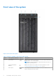
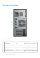
Table Of Contents
- Dell EMC PowerEdge T150 Installation and Service Manual
- Contents
- About this document
- PowerEdge T150 system overview
- Initial system setup and configuration
- Minimum to POST and system management configuration validation
- Installing and removing system components
- Safety instructions
- Before working inside your system
- After working inside your system
- Recommended tools
- System cover
- Frontbezel
- Drives
- Removing a 3.5-inch drive carrier from the drive bay
- Installing a 3.5-inch drive carrier into the drive bay
- Removing a drive from the drive carrier
- Installing a drive into the drive carrier
- Removing a 2.5-inch drive from the 3.5-inch drive adapter
- Installing a 2.5-inch drive into the 3.5-inch drive adapter
- Removing a 3.5-inch drive adapter from a 3.5-inch drive carrier
- Installing a 3.5-inch adapter into a 3.5-inch drive carrier
- Setting the cooling fan speed for 8 TB drives
- Cable routing
- Optional optical drive
- System memory
- Cooling fans
- Internal USB memory key
- Expansion cards
- Optional BOSS S1 card
- Processor and heat sink
- Power supply unit
- System battery
- Intrusion switch
- System board
- Trusted Platform Module
- Control panel
- Jumpers and connectors
- System diagnostics and indicator codes
- Getting help
- Documentation resources

Rear view of the system
Figure 2. Rear view of the system
Table 2. Rear view of the system
Item Ports, panels, or slots Icon Descriptions
1 Security cable lock N/A Enables you to connect to the security cable
lock.
2 iDRAC MAC address and iDRAC secure
password label
N/A Indicates the iDRAC MAC address and iDRAC
secure password label.
3 Service Tag, Express Service Code, QRL
label
N/A Indicates the Service Tag, Express Service
Code, QRL label.
4 OpenManage Mobile (OMM) label N/A Indicates the OpenManage Mobile (OMM) label.
5 PCIe expansion card slots (4) N/A Enables you to connect PCI Express expansion
cards.
10 PowerEdge T150 system overview