
Administrator Guide
The base C9010 configuration package consists of:
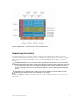
• One C9010 chassis
• One full-width C9000 Series RPM
– C9000-RPM-2.56T displays in SW output.
– 07KPC3 or 0N90RW is on the HW label.
• Three C9000 Series fan modules
– C9000-FAN displays in SW output.
– 0C94MF is on the HW label.
• One AC PSU (110-230V switching)
– C9000-PWR-AC displays in SW output.
– D3000E-S0 is on the HW label.
• AC power cord (IEC 60320 C19 cable)
• One DB-9 to RJ-45 serial console cable
• One rack bar with four screws and washers
• Eight cage nuts (four for the rack bar; four for the chassis thumb screws)
• Blank panels: one RPM, three PSU, and nine half-width line card blanks
• Two cable management brackets
• C9010 Getting Started Guide
• Safety and Regulatory Information
• Warranty and Support Information
• Software License Agreement
In addition, you can order the following items:
• Up to three additional PSUs for redundancy or additional power
• Half-width line cards:
– 6-Port 40 Gigabit Ethernet QSFP+ (C9000LC0640 displays in SW output.)
– 24-Port 1/10 Gigabit Ethernet SFP+ (C9000LC2410G displays in SW output.)
– 24-Port 1/10 Gigabit Ethernet Base-T RJ-45 (C9000LC2410T displays in SW output.)
• SFP+ optics
• QSFP+ optics
• SFP+ direct attach copper (DAC) cables
• QSFP+ DAC cables
• DB-9 adapter
• Dell ReadyRails™ kit (#1 and #2 Phillips and flat-tipped screwdrivers required) with four cage nuts
• Rack mount tray
• C1048P port extenders for use with the C9010
Before You Start: Site Preparation
Before installing the C9010 switch, make sure that your installation site meets these requirements:
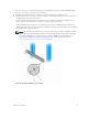
• Clearance: Ensure there is adequate space in front of the switch so you can read the light-emitting
diodes (LEDs) and adequate space around and behind the chassis for cabling, power connections,
6
C9010 Hardware Description