VRTX Chassis Diagnostics This white paper helps administrators to diagnose and troubleshoot the VRTX Chassis for any abnormalities in the modules listed (Power, PCIe Adapters, Servers, CMC, and Storage Components). VRTX Chassis logs the events on the different Logging Mechanisms such as SEL, LCD, and Chassis Log. It focusses on troubleshooting the events through the diagnostic commands and other troubleshooting techniques.
Executive summary VRTX chassis has different logging mechanism to capture all the events on the chassis. The event could be configuration change or any critical or non-critical. The VRTX Chassis has different logging mechanism like Chassis log, SEL Log, LCD, Remote System Logging. The events could be identified from the logs and the recommended action can be performed as stated on the logs, especially on the Chassis logs to overcome the critical events.
Introduction This white paper focusses on troubleshooting various chassis events by Diagnostic Console, LED Pattern, Recover commands, Component troubleshooting such as PSU, PCIe Adapter, Storage Controller, and Chassis Controller. This could be helpful for administrators to try few troubleshooting techniques during critical events.
ping The ping command is used to check the connectivity between systems in the network. When a Web connectivity is unable to connect to the VRTX Server on the Internet or LAN, the cause is often, because the Web server is not functioning, or it may be a network-related issue which hinders from connecting the host system. Therefore, the first step in diagnosing the problem is to test if the network connection is working. The ping command can be used in this situation without requiring a Web server.
racadm The racadm command is the Administration & Configuration command line utility on a VRTX Chassis. VRTX Chassis supports the following commands. Any help about a specific command can be obtained by running the command. racadm help . The syntax of the command is: racadm List of supported Racadm Commands on VRTX Chassis is given here.
getsensorinfo getslotname getssninfo getsvctag getsysinfo gettracelog getversion ifconfig jobqueue krbkeytabupload license netstat ping ping6 racdump racreset racresetcfg racresetpcie raid remoteimage --------------------- serveraction set setassettag setchassisname setflexaddr ------ setled setniccfg setpciecfg setractime setslotname setsysinfo sshpkauth sslcertdownload sslcertupload sslcertview sslcsrgen sslresetcfg testemail testfeature testtrap traceroute traceroute6 wsman ------------------- disp
Troubleshooting VRTX Components The following procedures describe how to troubleshoot the following components: Power supply modules Fan module CMC module Network switch module Troubleshooting Power Supply Modules The power supply modules are hot-pluggable. It is highly recommended to hot-plug one PSU at a time, because removal of two or more PSUs may cause the Chassis or the Server to automatically turn off on the basis of Power Supply Redundancy Configuration.
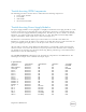
Switch-1 Server-1 Server-2 Server-3 Server-4 DVD IO-Cable FPC-Cable Present Present Present Present Present Not Present Present Present ON ON OFF OFF OFF N/A ON ON OK OK OK OK OK N/A OK OK N/A CFGBLD4 G1BPNW1 N/A N/A N/A PLST005 PLST005 In the getmodinfo command response, the PS-1..PS-4 Module indicates the power state and health condition of the PSU. If any of the PSUs is not functioning, it may indicate as Failed in the Power State, Critical or Not OK in Health. In that case, service the PSU.
Troubleshooting I/O Modules To eliminate the possibility of a hardware issue with the module or its attaching devices, make sure that the module is properly initialized and configured. Make sure that you have installed the module in an I/O slot that matches its fabric type. Check that the pass-through or switch module is cabled correctly.
To virtually reseat the server, in the Reset Server section, click Virtual Reseat in the Reset dropdown menu for the servers you want to reseat, and then click Apply Selections. This operation causes the servers to behave as if they were removed and reinserted. The following RACADM command can also be used to reseat servers: racadm serveraction –m reseat –f where n is the server number.
If the ‘*’ is not displayed for one of the configured servers, the settings may not be configured correctly. The output of this command contains detailed NTP statistics that may be useful in debugging the issue. If attempting to configure a Windows-based NTP server, it may help to increase the MaxDist parameter for ntpd. Before changing this parameter, understand all the implications, because the default setting must be large enough to work with most NTP servers.
Server IOM (Common) Green glowing Steadily Turned on Green Dark Turned off Blue, glowing steadily Normal Blue, blinking User-enabled module identifier Amber, glowing steadily Not used Amber, blinking Fault Blue, dark No Fault Green, glowing steadily Powered on Troubleshooting Non-responsive CMC VRTX Chassis unresponsiveness of CMC using any of the interfaces (the Web interface, Telnet, SSH, remote RACADM, or serial), you can diagnose by observing the LEDs on CMC, obtaining recovery informa
update file vrtx_cmc.bin. This is the same firmware image file used for normal firmware updates. The recovery process displays its current activity and boots to the CMC OS upon completion. When you type recover on the recovery prompt, the recover reason and available sub-commands display. An example of a recover sequence is given here. recover getniccfg recover setniccfg 192.168.0.120 255.255.255.0 192.168.0.1 recover ping 192.168.0.100 recover fwupdate -g -a 192.168.0.
Problem: Dynamic Power Supply Engagement (DPSE) is enabled, but none of the PSUs display in the Standby state. A. Resolution: There is insufficient surplus power. One or more PSUs are moved into the Standby state only when the surplus power available in the enclosure exceeds the capacity of at least one PSU. B. Resolution: DPSE cannot be fully supported with the PSUs present in the enclosure.
advised to remove the server and insert a supported server on the Chassis or upgrade the server to a version of firmware supporting the VRTX chassis, and then insert it back to the VRTX Chassis. Problem: Server is unable to turn on with Chassis Intrusion on Chassis log. Resolution: This may happen when the VRTX Chassis cover is open and the latch is not closed. It is advised to close the enclosure and latch it properly before a server turn-on command is issued.
7 N/A 8 N/A Empty N/A Unmapped Empty N/A Unmapped 9 1 cfg8s1mojo.bc.lab 9 2 SLOT-02 9 3 SLOT-03 9 4 SLOT-04 1 2 3 4 10 10 10 10 1 2 3 4 1 2 3 4 cfg8s1mojo.bc.lab SLOT-02 SLOT-03 SLOT-04 From the above command, administrators can view which PCIe slots are assigned to which server and the power state of the PCIe adapter. The server that is turned on may lead to the turning-on of the PCIe slots assigned to the server.
racadm raid get controllers: –p status FQDD can be obtained from the command above. A sample FQDD is RAID.ChassisIntegrated.1-1 Therefore the command is racadm raid get controllers:RAID.ChassisIntegrated.