
User's Manual

278 Troubleshooting and Recovery
Interpreting LED Colors and Blinking Patterns
The LEDs on the chassis provide information by color and blinking/no
blinking:
• Steadily glowing, green LEDs indicate that the component is powered on.
If the green LED is blinking, it indicates a critical but routine event,
such as a firmware upload, during which the unit is not operational. It
does not indicate a fault.
• A blinking amber LED on a module indicates a fault on that module.
• Blue, blinking LEDs are configurable by the user and used for
identification (see "Configuring LEDs to Identify Components on the
Chassis" on page 259).
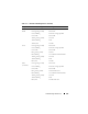
Table 11-11 lists common LED patterns on the chassis.
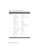
gettracelog Displays the trace log (may take a few seconds to display the
log). The gettracelog -i command returns the number of
records in the trace log. The gettracelog -A command returns
the trace log without the record numbers.
NOTE: This command is for Dell internal use only.
NOTE: For more information about the gettracelog command,
see "gettracelog" on page 322.
Table 11-11. LED Color and Blinking Patterns
Component LED Color, Blinking Pattern Meaning
CMC Green, glowing steadily Powered on
Green, blinking Firmware is being uploaded
Green, dark Powered off
Blue, glowing steadily Master/primary
Blue, blinking User-enabled module identifier
Amber, glowing steadily Not used
Amber, blinking Fault
Table 11-10. Supported Diagnostic Commands (continued)
Command Result