
User's Manual


274 I/O Fabric Management
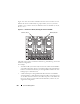
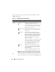
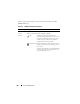
Figure 10-1 shows the location of IOMs in the chassis. The location of each
IOM in the chassis is indicated by its group number (A, B, or C) and slot
number (1 or 2). On the chassis, the IOM slot names are marked A1, A2, B1,
B2, C1, or C2.
Figure 10-1. Rear View of a Chassis, Showing the Location of the IOMs
The CMC creates entries in both the hardware log and CMC logs for invalid
hardware configurations.
For example:
• An Ethernet MC (mezzanine card) connected to a Fibre Channel IOM is
an invalid configuration. However, an Ethernet MC connected to both an
Ethernet switch and an Ethernet pass-through IOM installed in the same
IOM group is a valid connection.
• A Fibre Channel pass-through IOM and a fibre channel switch IOM in
slots B1 and B2 is a valid configuration if the first MCs on all of the servers
are also fibre channel. In this case, the CMC will power-on the IOMs and
the servers. However, certain fibre channel redundancy software may not
support this configuration.
Slots C2, B2, A2Slots A1, B1, C1