
Users Guide
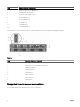
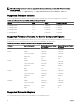
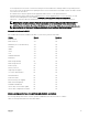

Item Indicator, Button, or Connector
3
Ethernet connector STK/Gb2 (stack)
4
System identification button
5
Low-profile PCIe expansion slots
6
Power supply (PSU1)
7
Power supply (PSU2)
8
I/O module (2)
9
I/O module ports
10
I/O module indicators
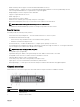
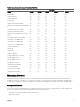
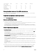
A Front Panel view of the chassis is given here with a table that lists the parts and devices available in the CMC.
Figure 2.
Item
Indicator, Button, or Connector
1
System identification button
2
Enclosure power-on indicator, power button
3
Diagnostic indicators
4
KVM select button
5
Compute sled
6
Video connector
7
USB connector
8
Storage sled
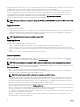
Supported remote access connections
The following table lists the supported remote access connections.
14