
Users Guide
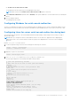
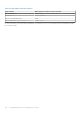
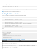
Table Of Contents
- Dell Chassis Management Controller Version 2.0 for PowerEdge FX2 and FX2s User's Guide
- Contents
- Overview
- Key Features
- Chassis overview
- Supported remote access connections
- Supported platforms
- Supported web browsers
- Supported firmware versions
- Supported Firmware Versions for Server Component Update
- Supported Network Adapters
- Managing licenses
- Viewing localized versions of the CMC web interface
- Supported management console applications
- How to use this Guide
- Other documents you may need
- Accessing support content from the Dell EMC support site
- Installing and setting up CMC
- Installing CMC hardware
- Checklist to set up chassis
- Daisy chain FX2 CMC network connection
- Using remote access software from a management station
- Remote RACADM installation
- Installing remote RACADM on a Windows management station
- Installing remote RACADM on a Linux management station
- Uninstalling remote RACADM from a Linux management station
- Configuring a web browser
- Downloading and updating CMC firmware
- Setting chassis physical location and chassis name
- Setting date and time on CMC
- Configuring LEDs to identify components on the chassis
- Configuring CMC properties
- Configuring front panel
- Configuring chassis management at server mode
- Installing CMC hardware
- Logging into CMC
- Configure public key authentication over SSH
- Accessing CMC web interface
- Logging into CMC as a local user, active directory user, or LDAP user
- Logging into CMC using a smart card
- Logging into CMC using Single Sign-On
- Logging into CMC using serial, Telnet, or SSH console
- Logging into CMC using public key authentication
- Multiple CMC sessions
- Updating firmware
- Signed CMC firmware image
- Downloading CMC firmware
- Viewing currently installed firmware versions
- Updating the CMC firmware
- Updating the CMC using DUP
- Updating chassis infrastructure firmware
- Updating server iDRAC firmware
- Updating server iDRAC firmware using web interface
- Updating server component firmware
- Enabling Lifecycle Controller
- Choosing server component firmware update type using CMC web interface
- Filtering components for firmware updates
- Viewing firmware inventory
- Saving chassis inventory report using CMC web interface
- Configuring network share using CMC web interface
- Lifecycle Controller job operations
- Reinstalling server component firmware
- Rolling back server component firmware
- Upgrading server component firmware
- Upgrading server component firmware from file using CMC web interface
- Server component single click update using network share
- Pre-requisites for using network share update mode
- Upgrading server component firmware from network share using CMC web interface
- Deleting Scheduled Server Component Firmware Jobs
- Recovering iDRAC firmware using CMC
- Viewing chassis information and monitoring chassis and component health
- Viewing chassis and component summaries
- Viewing chassis summary
- Viewing chassis controller information and status
- Viewing information and health status of all servers
- Viewing information and health status of storage sleds
- Viewing information and health status of the IOMs
- Viewing information and health status of fans
- Viewing front panel properties
- Viewing KVM information and health status
- Viewing information and health status of temperature sensors
- Configuring CMC
- Enabling or disabling DHCP for the CMC Network Interface Address
- Enabling or disabling DHCP for DNS IP addresses
- Setting static DNS IP addresses
- Viewing and modifying CMC network LAN settings
- Configuring IPv4 and IPv6 DNS settings
- Configuring auto negotiation, duplex mode, and network speed for IPv4 and IPv6
- Configuring Management Port 2
- Configuring Management Port 2 using RACADM
- Federal Information Processing Standards
- Configuring services
- Configuring CMC extended storage card
- Setting up Chassis Group
- Adding members to Chassis Group
- Removing a member from the leader
- Disbanding a Chassis Group
- Disabling an individual Member at the Member chassis
- Launching the web page of a Member chassis or server
- Propagating Leader chassis properties to Member chassis
- Synchronizing a new Member with Leader chassis properties
- Server inventory for MCM group
- Saving server inventory report
- Chassis Configuration Profiles
- Saving Chassis Configuration
- Restoring Chassis Configuration Profile
- Viewing Stored Chassis Configuration Profiles
- Importing Chassis Configuration Profiles
- Applying Chassis Configuration Profiles
- Exporting Chassis Configuration Profiles
- Editing Chassis Configuration Profiles
- Deleting Chassis Configuration Profiles
- Configuring Multiple CMCs through RACADM Using Chassis Configuration Profiles
- Configuring multiple CMCs using RACADM
- Configuring servers
- Configuring slot names
- Configuring iDRAC network settings
- Configuring iDRAC QuickDeploy network settings
- QuickDeploy IP address assignments for servers
- Modifying iDRAC Network Settings for individual server iDRAC
- Modifying iDRAC network settings using RACADM
- Configuring iDRAC VLAN tag settings
- Configuring iDRAC VLAN tag settings using web interface
- Configuring iDRAC VLAN tag settings using RACADM
- Setting first boot device
- Configuring sled network uplink
- Deploying remote file share
- Configuring server FlexAddress
- Configuring profile settings using server configuration replication
- Accessing Profile page
- Managing stored profiles
- Adding or saving profile
- Applying profile
- Importing profile
- Exporting profile
- Editing profile
- Viewing profile settings
- Viewing stored profile settings
- Viewing profile log
- Completion status and troubleshooting
- Quick Deploy of profiles
- Assigning server profiles to slots
- Boot Identity Profiles
- Saving Boot Identity Profiles
- Applying Boot Identity Profiles
- Clearing Boot Identity Profiles
- Viewing Stored Boot Identity Profiles
- Importing Boot Identity Profiles
- Exporting Boot Identity Profiles
- Deleting Boot Identity Profiles
- Managing Virtual MAC Address Pool
- Creating MAC Pool
- Adding MAC Addresses
- Removing MAC Addresses
- Deactivating MAC Addresses
- Launching iDRAC using Single Sign-On
- Launching remote console from server status page
- Configuring storage sleds
- Configuring CMC to send alerts
- Configuring user accounts and privileges
- Configuring CMC for Single Sign-On or Smart Card login
- System requirements
- Prerequisites for Single Sign-On or Smart Card login
- Generating Kerberos keytab file
- Configuring CMC for Active Directory schema
- Configuring browser for SSO login
- Configuring browser for Smart Card login
- Configuring CMC SSO login or Smart Card login for Active Directory users using RACADM
- Configuring CMC SSO Or Smart Card Login For Active Directory Users Using Web Interface
- Uploading Keytab file
- Configuring CMC SSO login or Smart Card login for Active Directory users using RACADM
- Configuring CMC to use Command Line consoles
- Using FlexAddress and FlexAddress Plus cards
- About FlexAddress
- Configuring FlexAddress
- Command messages
- FlexAddress DELL SOFTWARE LICENSE AGREEMENT
- Viewing WWN or MAC address information
- Viewing basic WWN or MAC address information using web interface
- Viewing advanced WWN or MAC address information using web interface
- Viewing WWN or MAC address information using RACADM
- Managing Fabrics
- Monitoring IOM health
- Configuring network settings for IOM
- Viewing Input Output module uplink and downlink status using web interface
- Viewing Input Output module FCoE session information using web interface
- Resetting IOM to factory default settings
- Updating IOM software using CMC web interface
- IOA or MXL GUI
- Input Output Aggregator Module
- Using VLAN Manager
- Assigning VLAN to IOM
- Configuring VLAN settings on IOMs using CMC web interface
- Viewing the VLAN settings on IOMs using CMC web interface
- Viewing the current VLAN settings on IOMs using CMC web interface
- Removing VLANs for IOMs using CMC web interface
- Updating untagged VLANs for IOMs using CMC web interface
- Resetting VLANs for IOMs using CMC web interface
- Managing and monitoring power
- Redundancy policies
- Default Redundancy configuration
- Multi-node sled adaptation
- Chassis power limit monitoring
- Viewing power consumption status
- Viewing power budget status using CMC web interface
- Viewing power budget status using RACADM
- Redundancy status and overall power health
- Configuring PCIe slots
- Troubleshooting and recovery
- Gathering configuration information, chassis status, and logs using RACDUMP
- Supported interfaces
- Downloading SNMP Management Information Base file
- First steps to troubleshoot a remote system
- Troubleshooting Alerts
- Viewing Event Logs
- Using Diagnostic Console
- Resetting Components
- Saving or Restoring Chassis Configuration
- Troubleshooting Network Time Protocol Errors
- Interpreting LED colors and blinking patterns
- Troubleshooting Network Problems
- General troubleshooting
- Resetting Forgotten Administrator Password
- Gathering configuration information, chassis status, and logs using RACDUMP
- Frequently asked questions

In a serial, Telnet, SSH console, CMC supports the connect command to establish a serial connection to a server or I/O
module. The server serial console contains both the BIOS boot and setup screens, and the operating system serial console. For
the I/O module, the switch serial console is available. There is a single IOM on the chassis.
CAUTION: When run from the CMC serial console, the connect -b option stays connected until the CMC
resets. This connection is a potential security risk.
NOTE: The connect command provides the –b (binary) option. The –b option passes raw binary data, and
cfgSerialConsoleQuitKey is not used. Additionally, when connecting to a server using the CMC serial console,
transitions in the DTR signal (for example, if the serial cable is removed to connect a debugger) will not result in you exiting
the application.
NOTE: If the IOM does not support console redirection, the connect command displays an empty console. In that case, to
return to the CMC console, type the Escape sequence. The default console escape sequence is <Ctrl><\>.
To connect to an IOM:
connect switch-n
where n is an IOM label A1.
When you reference the IOM in the connect command, the IOM is mapped to switch as shown in the following table.
Table 23. Mapping IO Module to Switches
IO Module Label Switch
A1 switch-a1 or switch- 1
A2 switch-a2 or switch- 2
NOTE: At a time, there can be only one IOM connection per chassis.
NOTE: You cannot connect to pass-throughs from the serial console.
To connect to a managed-server serial console, run the command connect server-n , where n = 1-4 (PowerEdge
FM120x4), and n = 1–8 (PowerEdge FC630). You can also use the racadm connect server-n command. When you
connect to a server using the -b option, binary communication is assumed and the escape character is disabled. If the iDRAC is
not available, the No route to host error message is displayed.
The connect server-n command enables the user to access the server's serial port. After this connection is established,
the user can view the server's console redirection through CMC's serial port that includes both the BIOS serial console and the
operating system serial console.
NOTE:
To view the BIOS boot screens, serial redirection has to be enabled in the servers’ BIOS setup. Also, you must set
the terminal emulator window to 80×25. Otherwise, the characters on the page are not properly displayed.
NOTE: All keys do not work on the BIOS setup pages. Therefore, provide appropriate keyboard shortcuts for <Ctrl> <Alt>
<Delete> and others. The initial redirection screen displays the necessary keyboard shortcuts.
Configuring the managed server BIOS for serial console redirection
You can use a Remote Console session to connect to the managed system using the iDRAC7 web interface (see the Dell
Integrated Dell Remote Access Controller (iDRAC) User’s Guide on dell.com/support/manuals).
By default, the Serial communication in the BIOS is turned off. To redirect host text console data to Serial over LAN, you must
enable console redirection through COM1. To change the BIOS setting:
1. Turn on the managed server.
2. Press the <F2> key to enter the BIOS setup utility during POST.
3. Go to Serial Communication, and then press <Enter> . In the dialog box, the serial communication list displays the
following options:
● off
● on without console redirection
114
Configuring CMC to use Command Line consoles