
Users Guide
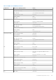
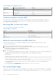
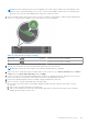
Table Of Contents
- Dell Chassis Management Controller Version 2.0 for PowerEdge FX2 and FX2s User's Guide
- Contents
- Overview
- Key Features
- Chassis overview
- Supported remote access connections
- Supported platforms
- Supported web browsers
- Supported firmware versions
- Supported Firmware Versions for Server Component Update
- Supported Network Adapters
- Managing licenses
- Viewing localized versions of the CMC web interface
- Supported management console applications
- How to use this Guide
- Other documents you may need
- Accessing support content from the Dell EMC support site
- Installing and setting up CMC
- Installing CMC hardware
- Checklist to set up chassis
- Daisy chain FX2 CMC network connection
- Using remote access software from a management station
- Remote RACADM installation
- Installing remote RACADM on a Windows management station
- Installing remote RACADM on a Linux management station
- Uninstalling remote RACADM from a Linux management station
- Configuring a web browser
- Downloading and updating CMC firmware
- Setting chassis physical location and chassis name
- Setting date and time on CMC
- Configuring LEDs to identify components on the chassis
- Configuring CMC properties
- Configuring front panel
- Configuring chassis management at server mode
- Installing CMC hardware
- Logging into CMC
- Configure public key authentication over SSH
- Accessing CMC web interface
- Logging into CMC as a local user, active directory user, or LDAP user
- Logging into CMC using a smart card
- Logging into CMC using Single Sign-On
- Logging into CMC using serial, Telnet, or SSH console
- Logging into CMC using public key authentication
- Multiple CMC sessions
- Updating firmware
- Signed CMC firmware image
- Downloading CMC firmware
- Viewing currently installed firmware versions
- Updating the CMC firmware
- Updating the CMC using DUP
- Updating chassis infrastructure firmware
- Updating server iDRAC firmware
- Updating server iDRAC firmware using web interface
- Updating server component firmware
- Enabling Lifecycle Controller
- Choosing server component firmware update type using CMC web interface
- Filtering components for firmware updates
- Viewing firmware inventory
- Saving chassis inventory report using CMC web interface
- Configuring network share using CMC web interface
- Lifecycle Controller job operations
- Reinstalling server component firmware
- Rolling back server component firmware
- Upgrading server component firmware
- Upgrading server component firmware from file using CMC web interface
- Server component single click update using network share
- Pre-requisites for using network share update mode
- Upgrading server component firmware from network share using CMC web interface
- Deleting Scheduled Server Component Firmware Jobs
- Recovering iDRAC firmware using CMC
- Viewing chassis information and monitoring chassis and component health
- Viewing chassis and component summaries
- Viewing chassis summary
- Viewing chassis controller information and status
- Viewing information and health status of all servers
- Viewing information and health status of storage sleds
- Viewing information and health status of the IOMs
- Viewing information and health status of fans
- Viewing front panel properties
- Viewing KVM information and health status
- Viewing information and health status of temperature sensors
- Configuring CMC
- Enabling or disabling DHCP for the CMC Network Interface Address
- Enabling or disabling DHCP for DNS IP addresses
- Setting static DNS IP addresses
- Viewing and modifying CMC network LAN settings
- Configuring IPv4 and IPv6 DNS settings
- Configuring auto negotiation, duplex mode, and network speed for IPv4 and IPv6
- Configuring Management Port 2
- Configuring Management Port 2 using RACADM
- Federal Information Processing Standards
- Configuring services
- Configuring CMC extended storage card
- Setting up Chassis Group
- Adding members to Chassis Group
- Removing a member from the leader
- Disbanding a Chassis Group
- Disabling an individual Member at the Member chassis
- Launching the web page of a Member chassis or server
- Propagating Leader chassis properties to Member chassis
- Synchronizing a new Member with Leader chassis properties
- Server inventory for MCM group
- Saving server inventory report
- Chassis Configuration Profiles
- Saving Chassis Configuration
- Restoring Chassis Configuration Profile
- Viewing Stored Chassis Configuration Profiles
- Importing Chassis Configuration Profiles
- Applying Chassis Configuration Profiles
- Exporting Chassis Configuration Profiles
- Editing Chassis Configuration Profiles
- Deleting Chassis Configuration Profiles
- Configuring Multiple CMCs through RACADM Using Chassis Configuration Profiles
- Configuring multiple CMCs using RACADM
- Configuring servers
- Configuring slot names
- Configuring iDRAC network settings
- Configuring iDRAC QuickDeploy network settings
- QuickDeploy IP address assignments for servers
- Modifying iDRAC Network Settings for individual server iDRAC
- Modifying iDRAC network settings using RACADM
- Configuring iDRAC VLAN tag settings
- Configuring iDRAC VLAN tag settings using web interface
- Configuring iDRAC VLAN tag settings using RACADM
- Setting first boot device
- Configuring sled network uplink
- Deploying remote file share
- Configuring server FlexAddress
- Configuring profile settings using server configuration replication
- Accessing Profile page
- Managing stored profiles
- Adding or saving profile
- Applying profile
- Importing profile
- Exporting profile
- Editing profile
- Viewing profile settings
- Viewing stored profile settings
- Viewing profile log
- Completion status and troubleshooting
- Quick Deploy of profiles
- Assigning server profiles to slots
- Boot Identity Profiles
- Saving Boot Identity Profiles
- Applying Boot Identity Profiles
- Clearing Boot Identity Profiles
- Viewing Stored Boot Identity Profiles
- Importing Boot Identity Profiles
- Exporting Boot Identity Profiles
- Deleting Boot Identity Profiles
- Managing Virtual MAC Address Pool
- Creating MAC Pool
- Adding MAC Addresses
- Removing MAC Addresses
- Deactivating MAC Addresses
- Launching iDRAC using Single Sign-On
- Launching remote console from server status page
- Configuring storage sleds
- Configuring CMC to send alerts
- Configuring user accounts and privileges
- Configuring CMC for Single Sign-On or Smart Card login
- System requirements
- Prerequisites for Single Sign-On or Smart Card login
- Generating Kerberos keytab file
- Configuring CMC for Active Directory schema
- Configuring browser for SSO login
- Configuring browser for Smart Card login
- Configuring CMC SSO login or Smart Card login for Active Directory users using RACADM
- Configuring CMC SSO Or Smart Card Login For Active Directory Users Using Web Interface
- Uploading Keytab file
- Configuring CMC SSO login or Smart Card login for Active Directory users using RACADM
- Configuring CMC to use Command Line consoles
- Using FlexAddress and FlexAddress Plus cards
- About FlexAddress
- Configuring FlexAddress
- Command messages
- FlexAddress DELL SOFTWARE LICENSE AGREEMENT
- Viewing WWN or MAC address information
- Viewing basic WWN or MAC address information using web interface
- Viewing advanced WWN or MAC address information using web interface
- Viewing WWN or MAC address information using RACADM
- Managing Fabrics
- Monitoring IOM health
- Configuring network settings for IOM
- Viewing Input Output module uplink and downlink status using web interface
- Viewing Input Output module FCoE session information using web interface
- Resetting IOM to factory default settings
- Updating IOM software using CMC web interface
- IOA or MXL GUI
- Input Output Aggregator Module
- Using VLAN Manager
- Assigning VLAN to IOM
- Configuring VLAN settings on IOMs using CMC web interface
- Viewing the VLAN settings on IOMs using CMC web interface
- Viewing the current VLAN settings on IOMs using CMC web interface
- Removing VLANs for IOMs using CMC web interface
- Updating untagged VLANs for IOMs using CMC web interface
- Resetting VLANs for IOMs using CMC web interface
- Managing and monitoring power
- Redundancy policies
- Default Redundancy configuration
- Multi-node sled adaptation
- Chassis power limit monitoring
- Viewing power consumption status
- Viewing power budget status using CMC web interface
- Viewing power budget status using RACADM
- Redundancy status and overall power health
- Configuring PCIe slots
- Troubleshooting and recovery
- Gathering configuration information, chassis status, and logs using RACDUMP
- Supported interfaces
- Downloading SNMP Management Information Base file
- First steps to troubleshoot a remote system
- Troubleshooting Alerts
- Viewing Event Logs
- Using Diagnostic Console
- Resetting Components
- Saving or Restoring Chassis Configuration
- Troubleshooting Network Time Protocol Errors
- Interpreting LED colors and blinking patterns
- Troubleshooting Network Problems
- General troubleshooting
- Resetting Forgotten Administrator Password
- Gathering configuration information, chassis status, and logs using RACDUMP
- Frequently asked questions

Table 33. LED Color and Blinking Patterns
Component LED Color, Blinking Pattern Status
Blue, blinking PCI identification is in progress.
Amber, blinking Fault
Storage sled Amber, blinking Fault
Solid Blue No fault
Troubleshooting Non-responsive CMC
If you cannot log in to CMC using any of the interfaces (the web interface, Telnet, SSH, remote RACADM, or serial), you
can verify the CMC functionality observing the LEDs on CMC, obtaining recovery information using the DB-9 serial port, or
recovering the CMC firmware image.
Observing LEDs to Isolate the Problem
The CMC has an LED which changes color to indicate:
Table 34. LED color indicators
Color Description
Blue Normal operation
Blue, blinking ID (0.5 second on, 0.5 second off)
Amber Chassis fault summary
Amber, blinking Chassis fault with concurrent ID
Obtain Recovery Information from DB-9 Serial Port
If the CMC LED is amber, recovery information is available from the DB-9 serial port located on the front of CMC.
To obtain recovery information:
1. Install a NULL modem cable between a CMC system and a client system.
2. Open a terminal emulator of your choice (such as HyperTerminal or Minicom). Enter the following specification when
prompted: 8 bits, no parity, no flow control, baud rate 115200.
A core memory failure displays an error message every 5 seconds.
3. Press the <Enter> key.
If a recovery prompt appears, additional information is available. The prompt indicates the CMC slot number and failure type.
To display failure reason and syntax for a few commands, type recover, and then press <Enter>.
Sample prompts:
recover1[self test] CMC self test failure
recover1[Bad FW images] CMC has corrupted images
● If the prompt indicates a self test failure, there are no serviceable components on CMC. CMC is bad and must be
returned to Dell.
● If the prompt indicates Bad FW Images, complete tasks in Recovering Firmware Image1.
Recovering Firmware Image
CMC enters recover mode when a normal CMC operating boot is not possible. In recover mode, a small subset of commands are
available that allow you to reprogram the flash devices by uploading the firmware update file, fx2_cmc.bin. This is the same
152
Troubleshooting and recovery