Dell FluidFS Version 6.
Notes, Cautions, and Warnings NOTE: A NOTE indicates important information that helps you make better use of your product. CAUTION: A CAUTION indicates either potential damage to hardware or loss of data and tells you how to avoid the problem. WARNING: A WARNING indicates a potential for property damage, personal injury, or death. Copyright © 2017 Dell Inc. or its subsidiaries. All rights reserved. Dell, EMC, and other trademarks are trademarks of Dell Inc. or its subsidiaries.
Contents About This Guide............................................................................................................... 5 Revision History..................................................................................................................................................................5 Audience............................................................................................................................................................................
Configure the FluidFS Cluster....................................................................................... 27 Configure FluidFS Cluster Network Settings.................................................................................................................... 27 Connect to the FluidFS Cluster CLI ........................................................................................................................... 27 Configure Cluster IP Addresses and the Default Gateway............
About This Guide This guide provides information about deploying an FS8600 appliance in a clustered, scale-out NAS environment. Revision History Document number: 690-047-005 Revision Date Description A February 2017 Initial release of FluidFS v6 Audience The target audience for this document is Dell installers and certified business partners who perform FS8600 appliance installations. Related Publications The following documents comprise the core Dell FS8600 appliance documentation set.
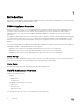
1 Introduction Deploying the FS8600 appliance includes installing the appliance hardware, connecting the FS8600 appliance to the Storage Centers and the client network, and configuring the FluidFS cluster. FS8600 Appliance Overview FS8600 scale-out NAS consists of one to four FS8600 appliances configured as a FluidFS cluster. Each NAS appliance is a rackmounted 2U chassis that contains two hot-swappable NAS controllers in an active-active configuration.
Figure 1. FS8600 Scale-Out NAS Architecture Storage Center The Storage Center provides the FS8600 scale-out NAS storage capacity. The FS8600 cannot be used as a standalone NAS appliance, which eliminates the need to have separate storage capacity for block and file storage. In addition, Storage Center features, such as Dynamic Capacity and Data Progression, are automatically applied to NAS volumes.
SAN Network The FS8600 shares a back-end infrastructure with the Storage Center. The SAN network connects the FS8600 to the Storage Center and carries the block-level traffic. The FS8600 communicates with the Storage Center using either the iSCSI or Fibre Channel protocol, depending on which NAS appliance configuration you purchased.
2 Deployment Prerequisites Verify that the prerequisites are met before proceeding with the deployment process. Rack and Infrastructure Make sure the rack space and related infrastructure are available for the FS8600 appliances. ■ Prerequisite □ 2U rack space for each FS8600 appliance in an industry-standard 48.3 cm (19 inch) rack • • • • • • □ The rack must be four-post, square-hole or round-hole, and tool-less. The rack must be rated for 540 kg (1200 pounds) static load or greater.
■ Prerequisite □ Cables for internal network □ • Fibre Channel with 1GbE appliance: • – Single appliance – Four RJ45/Cat 5e or better cables for each appliance (controllers are directly connected to each other) – Multiple appliances – Eight RJ45/Cat 5e or better cables for each appliance Fibre Channel with 10GbE appliance: • – Single appliance – Two LC optical fiber cables or twinax cables (controllers are directly connected to each other; two Twinax cables shipped with each appliance) – Multiple
SAN and Internal Network for Fibre Channel Appliances The following prerequisites apply to Fibre Channel with 1GbE appliances and Fibre Channel with 10GbE appliances. Fibre Channel SAN Fabric Make sure the Fibre Channel SAN fabric is ready for deployment. ■ Prerequisite □ Fibre Channel switches can be reached from the rack. • • □ At least one switch must be available to connect the FluidFS cluster to the Storage Center. An FS8600 appliance cannot be connected directly to a Storage Center.
SAN and Internal Networks for iSCSI Appliances The following prerequisites apply to 10GbE iSCSI appliances. For these appliances, the iSCSI network and internal network share 10GbE ports and switch infrastructure. ■ Prerequisite □ 10GbE switches can be reached from the rack. • • • At least one switch must be available to connect the FluidFS cluster to the Storage Center. An FS8600 appliance cannot be connected directly to a Storage Center.
■ Prerequisite • □ If jumbo frames are used on the client network, the switches and clients must be configured to use MTU 9000. (Recommended but not required) Flow control is enabled on the switches. IP Addresses and Network Infrastructure Reserve IP addresses for the FluidFS cluster and record relevant network infrastructure information.
■ Prerequisite • • An SC4020 storage system requires Storage Center 6.5.10 or later. An SCv2080 storage system requires Storage Center 6.6.4 or later. NOTE: A single FluidFS cluster supports up to eight Storage Centers. • • For deployment instructions, see the Dell Storage Center Deployment Guide. For upgrade instructions, see the Dell Storage Center Software Update Guide.
3 Install and Connect the FS8600 Hardware Install the FS8600 appliances in a rack and connect the SAN, internal, and client networks. Install the FS8600 Hardware Unpack the hardware and mount it in a rack. Prerequisites The rack must meet the prerequisites listed in Rack and Infrastructure. Steps 1. Unpack the hardware. 2.
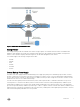
Figure 2. FC FS8600 Appliance Ports (1GbE) 2. 1. Client network ports 3. Fibre Channel ports 2. Internal network ports Connect each appliance to the Fibre Channel SAN fabric. • For each controller, use LC optical fiber cables to connect both Fibre Channel ports to the fabric. • 3. If the cluster has two Fibre Channel fabrics (Storage Center fault domains), make sure each controller is connected to both fabrics. Connect each appliance to the internal network.
Figure 3. Single-Appliance Fibre Channel 1GbE Cluster Configuration With an SC9000 Storage System 1. Client network 2. Internal network 3. Fibre Channel SAN switch 4. SC9000 with 1Gb FC ports 5. Client network connections 6. FS8600 internal network connections 7. Storage Center fault domain 1 connections 8.
Figure 4. Multi-Appliance Fibre Channel 1GbE Cluster Configuration With an SC8000 Storage System 1. Client network 2. Internal network 3. Fibre Channel SAN switch 4. SC8000 with 1Gb FC ports 5. Client network connections 6. Internal network connections 7. Storage Center fault domain 1 connections 8.
Steps 1. Identify the ports on an FC FS8600 appliance (10GbE). Figure 5. FC FS8600 Appliance Ports (10GbE) 2. 1. Client network ports 3. Fibre Channel ports 2. Internal network ports Connect each appliance to the Fibre Channel SAN fabric. • For each controller, use LC optical fiber cables to connect both Fibre Channel ports to the fabric. • 3. If the cluster has two Fibre Channel fabrics (Storage Center fault domains), make sure each controller is connected to both fabrics.
Figure 6. Single-Appliance Fibre Channel 10GbE Cluster Configuration With an SC4020 Storage System 1. Client network 2. Internal network 3. Fibre Channel SAN switch 4. SC4020 with 10Gb FC ports 5. Client network connections 6. FS8600 internal network connections 7. Storage Center fault domain 1 connections 8.
Figure 7. Multi-Appliance Fibre Channel 10GbE Cluster Configuration With an SCv2080 Storage System 1. Client network 2. Internal network 3. Fibre Channel SAN switch 4. SCv2080 with 10Gb FC ports 5. Client network connections 6. Internal network connections 7. Storage Center fault domain 1 connections 8. Storage Center fault domain 2 connections Configure Network Connections for 10GbE iSCSI Appliances Connect 10GbE iSCSI appliances to the SAN/internal network and client network.
Figure 8. 10GbE iSCSI FS8600 Appliance Ports 1. 2. Client network ports 2. Internal/iSCSI ports Connect each appliance to the SAN/internal network. • Use LC optical fiber or twinax cables to connect all controller internal/iSCSI ports to the SAN/internal network Ethernet switches. – For all controllers, eth30 (upper right port), must be connected to the same subnet. – For all controllers, eth31 (lower right port), must be connected to the same subnet. 3.
Figure 9. 10GbE iSCSI Cluster Configuration With an SC9000 Storage System 1. Client network 2. Internal/iSCSI SAN switch 3. SC9000 with 10GbE iSCSI ports 4. Client network connections 5. Untagged VLAN – FS8600 internal network connections 6. VLAN Storage Center SAN A connections 7.
Figure 10. 10GbE iSCSI Cluster Configuration With an SC8000 Storage System 1. Client network 2. Internal/iSCSI SAN switch 3. SC8000 with 10GbE iSCSI ports 4. Client network connections 5. Untagged VLAN – FS8600 internal network connections 6. VLAN Storage Center SAN A connections 7.
Figure 11. 10GbE iSCSI Cluster Configuration With an SC4020 Storage System 1. Client network 2. Internal/iSCSI SAN switch 3. SC4020 with 10GbE iSCSI ports 4. Client network connections 5. Untagged VLAN – FS8600 internal network connections 6. VLAN Storage Center SAN A connections 7.
Figure 12. 10GbE iSCSI Cluster Configuration With an SCv2080 Storage System 1. Client network 2. Internal/iSCSI SAN switch 3. SCv2080 with 10GbE iSCSI ports 4. Client network connections 5. Untagged VLAN – FS8600 internal network connections 6. VLAN Storage Center SAN A connections 7.
4 Configure the FluidFS Cluster Set the initial IP address for the first FS8600 appliance, then use Dell Storage Manager to configure the FluidFS cluster. Configure FluidFS Cluster Network Settings Use the CLI to configure initial IP addresses for the first appliance. Connect to the FluidFS Cluster CLI Connect to the FluidFS cluster CLI using either a VGA console or the iBMC virtual KVM. Connect to the FluidFS Cluster CLI Using a VGA Console Log in to the CLI using a VGA console.
3. Open a web browser on the laptop. In the address bar of the web browser, type http://192.168.254.253. The iBMC login page opens. 4. Log in to the iBMC. The user name is ADMIN and the password is N@sst0r3. 5. Click Launch Java KVM Client. The FluidFS cluster CLI opens. 6. From the command line, type the following command at the next login as prompt: cli 7. Type the FluidFS cluster administrator user name at the login as prompt. The default user name is Administrator. 8.
Log In to Dell Storage Manager Use the Dell Storage Manager Client to log in to the Dell Storage Manager Data Collector. Prerequisites The Dell Storage Manager user account must have the Administrator privilege to view, manage, or add FluidFS clusters in the Dell Storage Manager Client. Steps 1. Start the Dell Storage Manager Client application. 2. In the User Name field, type the Dell Storage Manager Data Collector user name. 3.
Figure 14. Add FluidFS Cluster Wizard — Select Appliances Page Steps 1. Add or remove appliances from the cluster. • To add an appliance, select an appliance in the upper pane, then click Add Appliance. • To remove an appliance, select an appliance in the lower pane, then click Remove Appliance. NOTE: All appliances in a single cluster must be the same model. 2. Click Next. The Configure Client Network page opens. Configure the Client Network Add the remaining client VIPs and controller IP addresses.
Figure 16. Edit Client Network Settings Steps 1. Confirm that the Netmask or Prefix Length and VLAN Tag fields display the correct netmask or prefix length and VLAN ID for the client network. Modify these fields if necessary. 2. 3. 4. In the Virtual IP Addresses table, define additional client VIPs for the cluster. To add a VIP, click Add, type the IP address in the dialog box, and then click OK.
Steps 1. Click the Storage view and select a FluidFS cluster. 2. In the File System view, select Cluster Connectivity, and click the Client Network tab. 3. In the Static Route panel, click Configure Default Gateway. The Configure Default Gateway dialog box opens. 4. In the Default IPvn Gateway field, type a new default gateway IP address. To provide a default gateway for IPv4 and IPv6 addresses, you need a client subnet of the appropriate type that contains the default gateway. 5. Click OK.
Figure 19. Add FluidFS Cluster Wizard — Configure Time Settings Page Steps 1. From the Time Zone drop-down menu, select the time zone where the FluidFS cluster is located. 2. (Optional) Configure the cluster to synchronize time with one or more NTP servers. a. b. c. d. e. 3. Add an NTP server by typing a host name or IP address in the field and clicking Add. Select the Set Time Using NTP Enabled checkbox. If the time displayed in the Current Time field is correct, click OK.
• If the FluidFS cluster has Fibre Channel appliances, the Connectivity Report page opens. See Configure Fibre Channel SAN Connectivity. • If the FluidFS cluster has 10GbE iSCSI appliances, the Select iSCSI Fault Domains page opens. See Configure iSCSI SAN Connectivity. Configure Fibre Channel SAN Connectivity Record the FluidFS World Wide Names and configure Fibre Channel zoning to allow the FluidFS cluster FC ports to communicate with the Storage Center front-end FC ports.
Verify Fibre Channel Connectivity Use the Connectivity Report page to verify that each FluidFS Fibre Channel port has connectivity to the Storage Centers. About this task Use this page of the Add FluidFS Cluster wizard to verify Fibre Channel connectivity to Storage Centers. Figure 22. Add FluidFS Cluster Wizard — Verify Fibre Channel Connectivity Page Steps 1. Click Refresh. • If zoning is configured correctly, the status for each port changes to Up. • 2.
Figure 23. Add FluidFS Cluster Wizard — Select iSCSI Fault Domains Steps 1. Select a Storage Center iSCSI control port for each connected subnet (Storage Center fault domain). 2. Click Next. The Configure IP Addresses for NAS Controller iSCSI HBAs page opens. Configure IP Addresses for NAS Controller iSCSI HBAs Use the Configure IP Addresses for NAS Controller iSCSI HBAs page to configure IP addresses for each iSCSI HBA.
a. b. c. d. Next to iSCSI Targets, locate the Storage Center iSCSI target IP addresses. Based on these IP addresses, identify the iSCSI subnet (Storage Center fault domain). In the VLAN Tag field, type the VLAN ID for the subnet (fault domain). From the Interface drop-down menu, select the controller interface that is connected to the iSCSI subnet. • eth30 / SAN is the upper right port in each controller. • eth31 / SAN b is the lower right port in each controller. e.
Figure 26. Add FluidFS Cluster Wizard — Connectivity Report (Up) 2. If the iSCSI configuration is correct, proceed to step 3. Otherwise, perform the following steps to modify the iSCSI configuration. After you are past the Connectivity Report page, you will no longer be able to modify the iSCSI configuration using the Add FluidFS Cluster wizard. a. Close the Add FluidFS Cluster wizard by clicking the Close (x) button in the top-right corner of the wizard. The Summary tab is displayed. Figure 27.
Figure 28. Add FluidFS Cluster Wizard — Existing iSCSI Configuration Page c. Select Remove existing iSCSI Configuration. d. Click Next. The Select Storage Centers page opens. See Select Storage Centers. 3. Click Next. The Configure NAS Pool page opens. Finalize FluidFS Cluster Configuration Define the NAS pool size, configure optional external directory service integration, and change the administrator password.
Steps 1. In the NAS Pool Size field, type the amount of block storage to provide for NAS volumes in gigabytes (GB) or terabytes (TB). The minimum NAS pool size is 1 TB. For information about maximum NAS pool sizes, see the Dell Fluid File System Version 6.0 Support Matrix. NOTE: • The usable FluidFS NAS pool is smaller due to FluidFS overhead. For example, if a single appliance cluster with a 2-TB pool is created, the actual NAS pool size is about 1.6 TB (roughly 400-GB overhead).
• If you did not close the Add FluidFS Cluster wizard while adding the FluidFS cluster, the Join Active Directory Domain page opens. See Join the Active Directory Domain. • If you closed and reopened the Add FluidFS Cluster wizard while adding the FluidFS cluster, the Change Administrator Password page opens. See Change the Administrator Password. The Active Directory and NIS/LDAP pages of the wizard are not displayed. The Active Directory and NIS/LDAP settings must be configured as a post-setup task.
Configure NIS Settings Adding multiple NIS servers ensures continued authentication of clients in the event of a resource outage. If the FluidFS cluster cannot establish contact with a server, it attempts to connect to the remaining servers. About this task Use this page of the Add FluidFS Cluster wizard to configure external authentication. Figure 33. Add FluidFS Cluster Wizard — Configure External User Database Page Steps 1. In the NIS Domain Name field, type an NIS domain name. 2. 3.
• • • Anonymous LDAP – The connection from the FluidFS cluster to the LDAP servers is not authenticated. The data is sent in plain text. Authenticated LDAP – The connection from the FluidFS cluster to the LDAP servers is authenticated using a user name and password. The data is sent in plain text. LDAP over TLS/SSL – The connection from the FluidFS cluster to the LDAP servers is authenticated and encrypted.
Steps 1. To change the default Administrator password, type a password for the Administrator account in the Password field. 2. In the Confirm Password field, retype the password. 3. To set a Support User password, type a password in the Password field. 4. In the Confirm Password field, retype the password. 5. Select or deselect the Support Access Enabled checkbox. 6. Click Finish. The FluidFS cluster is added to Dell Storage Manager and displayed on the Storage view.
5 Perform Post-Setup Tasks Complete the deployment by performing these post-setup tasks. All tasks are optional. Add DNS Records for the FluidFS Cluster If clients access the FluidFS cluster by name, add an entry in the DNS server that associates the FluidFS cluster name to the FluidFS cluster client VIPs. • If you are in a routed client network and using multiple client VIPs, add all client VIPs to the DNS server and associate them with the same FluidFS cluster name (set up round-robin DNS).
Add a Secured Management Subnet The subnet on which you enable secured management must exist prior to enabling the secured management feature. 1. In the Storage view, select a FluidFS cluster. 2. Click the File System tab. 3. In the File System view, select Cluster Connectivity, and then click the Management Network tab. 4. In the Management Network panel, click Edit Settings. The Modify Administrative Network dialog box opens. 5.
The Modify Administrative Network dialog box opens. 5. Enable or disable secured management. From the State drop-down list: • 6. To enable secured management, select Restricted or Unrestricted. • To disable secured management, select Disabled. Click OK. Verify That Dell Storage Manager Is Receiving FluidFS Events FluidFS errors and operations are reported to the Dell Storage Manager Client. Verify that errors and activities are being reported. 1.
• 48 Configure replication to a remote FluidFS cluster Perform Post-Setup Tasks
A Upgrade an Appliance to the Latest FluidFS 6.0 Version If an FS8600 appliance was imaged with FluidFS v5.0 or an early version of FluidFS v6.0 at the factory and will be deployed running FluidFS v6.0, upgrade the standby controllers to the latest version before configuring them as part of a FluidFS v6.0 cluster. NOTE: This procedure does not update the internal USB drive in the FS8600 controllers. Upgrade Prerequisites Make sure the following prerequisites are met before beginning the upgrade procedure.
b. Copy the DellFluidFS-6.0.xxyyyy.iso file to the servicepack folder. 4. Flash the controller to the new version: a. Wait for about 10 minutes until the new FluidFS version shows up as Not installed in the following list: CLI> maintenance software-updates list b. Initiate the upgrade using the following CLI command: CLI> maintenance software-updates flash-standby-controller filename 5. Wait for up to 30 minutes until the controller is up and running again.
B iSCSI Switch Configuration Examples These examples shows how to configure the switch that is used to connect a 10GbE iSCSI appliance to the SAN/internal network. Dell PowerConnect iSCSI Switch Configuration This example shows how to cable and configure a Dell PowerConnect 8024F switch to connect an FS8600 10GbE iSCSI appliance to the SAN/internal network. This example uses the best-practices configuration, which includes dual switches and dual iSCSI SANs. Figure 38.
Dell Force10 S5000 iSCSI Switch Configuration This example shows how to cable and configure a Dell Force10 S5000 switch to connect an FS8600 10GbE iSCSI appliance to the SAN/internal network. This example uses the best-practices configuration, which includes dual switches and dual iSCSI SANs. Figure 39. Dell Force10 S5000 Switch and FS8600 10GbE iSCSI Appliance Configuration 1. FS8600 10GbE iSCSI 2. F10 S5000–SAN-A 3. F10 S5000–SAN-B 4. VLAN 30 for SAN A 5. VLAN 31 for SAN B 6.