Dell Vostro 3905 Owner's Manual Regulatory Model: D17M Regulatory Type: D17M002
Notes, cautions, and warnings NOTE: A NOTE indicates important information that helps you make better use of your computer. CAUTION: A CAUTION indicates either potential damage to hardware or loss of data and tells you how to avoid the problem. WARNING: A WARNING indicates a potential for property damage, personal injury, or death. Copyright © 2015 Dell Inc. All rights reserved. This product is protected by U.S. and international copyright and intellectual property laws.
Contents 1 Working on Your Computer................................................................................5 Before Working Inside Your Computer................................................................................................ 5 Turning Off Your Computer..................................................................................................................6 After Working Inside Your Computer......................................................................................
Installing the System Board................................................................................................................ 23 System Board Components................................................................................................................23 3 Troubleshooting Your Computer.................................................................... 25 Diagnostic Power LED Codes.....................................................................................................
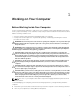
Working on Your Computer 1 Before Working Inside Your Computer Use the following safety guidelines to help protect your computer from potential damage and to help to ensure your personal safety. Unless otherwise noted, each procedure included in this document assumes that the following conditions exist: • You have read the safety information that shipped with your computer. • A component can be replaced or--if purchased separately--installed by performing the removal procedure in reverse order.
CAUTION: To disconnect a network cable, first unplug the cable from your computer and then unplug the cable from the network device. 3. Disconnect all network cables from the computer. 4. Disconnect your computer and all attached devices from their electrical outlets. 5. Press and hold the power button while the computer is unplugged to ground the system board. 6. Remove the cover.
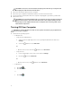
2. 2. Click the arrow in the lower-right corner of the Start menu as shown below, and then click Shut Down . Ensure that the computer and all attached devices are turned off. If your computer and attached devices did not automatically turn off when you shut down your operating system, press and hold the power button for about 6 seconds to turn them off.
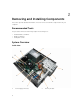
Removing and Installing Components This section provides detailed information on how to remove or install the components from your computer. Recommended Tools The procedures in this document may require the following tools: • Small flat-blade screwdriver • Phillips screwdriver • Small plastic scribe System Overview Inside view 1. 8 Power Supply Unit (PSU) 2.
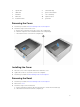
3. optical drive 4. card-reader bay 5. I/O board 6. power-switch board 7. hard drive 8. coin-cell battery 9. VGA card 10. expansion card 11. heatsink module 12. system fan Removing the Cover 1. Follow the procedures in Before Working Inside Your Computer. 2. Follow the steps to remove the cover: a. Remove the screws that secure the cover to the computer [1]. b. Slide the computer cover towards the back of the computer [2]. c. Lift and remove the cover from the computer [3].
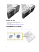
Installing the Bezel 1. Insert the bezel on the computer aligning it to the placeholders. 2. Press the bezel until the hooks snap in to place. 3. Install the cover. 4. Follow the procedures in After Working Inside Your Computer. Removing the Coin-Cell Battery 1. Follow the procedures in Before Working Inside Your Computer. 2. Remove the cover. 3. Push the coin-cell release latch and pull the coin-cell battery to remove it from the computer.
Installing the Coin-Cell Battery 1. Place the coin-cell battery on the system board until it snaps in place. 2. Install the cover. 3. Follow the procedures in After Working Inside Your Computer. Removing the Hard-Drive Assembly 1. Follow the procedures in Before Working Inside Your Computer. 2. Remove the: • 3. cover • bezel Follow the steps to remove the hard-drive assembly from the computer: a. Disconnect the SATA cable and power cable from the hard drive [1] [2]. b.
Installing the Hard-Drive Assembly 1. Replace the hard drive into the hard-drive bracket. 2. Install the screws that secure the hard-drive bracket. 3. Install the hard-drive assembly into its slot on the computer. 4. Install the screws that secure the hard-drive assembly to the computer. 5. Connect the SATA cable and the power cable to the hard-drive assembly. 6. Install the: • 7. bezel • cover Follow the procedures in After Working Inside Your Computer. Removing the Optical Drive 1.
Installing the Optical Drive 1. Push the optical drive into the optical-drive bay until it snaps into place. 2. Tighten the screws to secure the optical drive to the computer. 3. Connect the data cable and power cable to their connectors on the optical drive. 4. Install the: • 5. bezel • cover Follow the procedures in After Working Inside Your Computer. Removing the Card Reader 1. Follow the procedures in Before Working Inside Your Computer. 2. Remove the: • 3.
Installing the Card Reader 1. Slide the card reader into its slot until it snaps into place. 2. Tighten the screws to secure the card reader to the computer. 3. Thread the card reader power cable through the metal clip. 4. Connect the power cable of the card reader to the system board. 5. Install the: • 6. bezel • cover Follow the procedures in After Working Inside Your Computer. Removing the Memory 1. Follow the procedures in Before Working Inside Your Computer. 2. Remove the cover. 3.
Installing the Memory 1. Align the notch on the memory card with the tab in the memory connector. 2. Insert the memory module into the memory socket. 3. Press down on the memory module until the memory-retention tabs secure the memory in place. 4. Install the cover. 5. Follow the procedures in After Working Inside Your Computer. Removing the Heatsink Module 1. Follow the procedures in Before Working Inside Your Computer. 2. Remove the cover. 3.
4. Lift the processor to remove it from the computer. Installing the Processor 1. Install the processor into the socket. NOTE: To install the processor correctly in to the socket, align the processor to its position as displayed in the image. 2. Press down the processor to secure it inside the socket. 3. Push the release lever down and then press it inward to hold the retention hook that secures it. 4.
5. Follow the procedures in After Working Inside Your Computer. Removing the Expansion Card(s) 1. Follow the procedures in Before Working Inside Your Computer. 2. Remove the cover. 3. Follow the steps to remove the expansion card: a. Press the blue tab [1] and slide down the release lever that secures the expansion card [2]. b. Press the retaining tab to release the expansion card from its connector [3]. c. Lift the expansion card from the connector and remove it from the computer [4]. 4.
4. Follow the steps to remove the power supply unit: a. Remove the screws that secure the power supply unit to the computer. b. Push-in on the blue release tab at the base of the power supply unit [1]. c. Slide the power supply unit towards the back and remove it from the computer [2]. Installing the Power Supply Unit (PSU) 1. Slide the PSU towards the back of the computer until it snaps into place. 2. Replace the screws to secure the power supply unit to the computer. 3.
• 3. cover • bezel Follow the steps to remove the power switch: a. Disconnect the power-switch cable from the system board [1]. b. Un-thread the power-switch cable from the metal-retention clips [2]. 4. Remove the power switch by pressing on the two tabs [1] and pulling it out from the slot. Installing the Power Switch 1. Insert the power-switch cable through the front of the computer. 2. Push the power switch into its slot and press it in, until it snaps into place. 3.
4. Connect the power-switch cable to the connector on the system board. 5. Install the: • 6. bezel • cover Follow the procedures in After Working Inside Your Computer. Removing the Input/Output (I/O) Panel 1. Follow the procedures in Before Working Inside Your Computer. 2. Remove the: • 3. cover • bezel Follow the steps to remove the I/O panel cables: a. Disconnect the I/O panel and FlyWire cables from the system board [1, 3]. b. Un-thread the cables from the metal-retention clips [2, 4]. 4.
Installing the Input/Output (I/O) Panel 1. Slide the I/O panel into its slot on the computer. 2. Tighten the screw to secure the I/O panel to the computer. 3. Route the cables through the metal-rentention clips. 4. Connect the I/O panel and FlyWire cables to their connectors on the system board. 5. Install the: • 6. bezel • cover Follow the procedures in After Working Inside Your Computer. Removing the System Fan 1. Follow the procedures in Before Working Inside Your Computer. 2.
Installing the System Fan 1. Place the system fan on the computer. 2. Tighten the screws to secure the system fan to the computer. 3. Connect the system-fan cable to the connector on the system board. 4. Install the cover. 5. Follow the procedures in After Working Inside Your Computer. Removing the System Board 1. Follow the procedures in Before Working Inside Your Computer. 2. Remove the: 3.
Installing the System Board 1. Place the system board into the computer securely until it snaps in place. 2. Tighten the screws to secure the system board to the computer. 3. Thread and connect all the cables to the system board. 4. Install the: • 5. I/O panel • memory • expansion cards • processor • heatsink • hard-drive assembly • optical drive • bezel • cover Follow the procedures in After Working Inside Your Computer.
1. PCIe x1 connector 2. PCIe x16 connector 3. PCIe x1 connector 4. system fan connector 5. P2 power connector 6. processor socket 7. processor-fan connector 8. memory connectors 9. P1 power connector 10. front USB connector 11. real-time clock reset jumper 12. password reset jumper 13. card reader connector 14. coin-cell battery 15. SATA connectors 16. power-switch connector 17. SATA connectors 18.
Troubleshooting Your Computer 3 You can troubleshoot your computer using indicators like Diagnostic Lights, Beep Codes, and Error Messages during the operation of the computer. Diagnostic Power LED Codes Table 1. Diagnostic power LED codes Power Possible Cause LED Light Status Troubleshooting Steps Off • The computer is either turned off or is not receiving power or in Hibernation mode. • • Steady / Blinking Amber Computer fails to complete POST or processor failure.
Diagnostic Error Messages Table 2. Diagnostic error messages Error Messages Description AUXILIARY DEVICE FAILURE The touchpad or external mouse may be faulty. For an external mouse, check the cable connection. Enable the Pointing Device option in the system setup program. BAD COMMAND OR FILE NAME Ensure that you have spelled the command correctly, put spaces in the proper place, and used the correct pathname. CACHE DISABLED DUE TO FAILURE The primary cache internal to the microprocessor has failed.
Error Messages Description HARD-DISK DRIVE CONFIGURATION ERROR The computer cannot identify the drive type. Shut down the computer, remove the hard drive, and boot the computer from an optical drive. Then, shut down the computer, reinstall the hard drive, and restart the computer. Run the Hard Disk Drive tests in the Dell Diagnostics. HARD-DISK DRIVE CONTROLLER FAILURE 0 The hard drive does not respond to commands from the computer.
Error Messages Description KEYBOARD DATA LINE FAILURE For external keyboards, check the cable connection. Run theKeyboard Controller test in the Dell Diagnostics. KEYBOARD STUCK KEY FAILURE For external keyboards or keypads, check the cable connection. Restart the computer, and avoid touching the keyboard or keys during the boot routine. Run the Stuck Key test in the Dell Diagnostics.
Error Messages Description OPTIONAL ROM BAD CHECKSUM The optional ROM has failed. Contact Dell. SECTOR NOT FOUND The operating system cannot locate a sector on the hard drive. You may have a defective sector or corrupted FAT on the hard drive. Run the Windows error-checking utility to check the file structure on the hard drive. See Windows Help and Support for instructions (click Start > Help and Support).
System Error Messages Table 3. System error messages System Message Description Alert! Previous attempts at booting this system The computer failed to complete the boot routine have failed at checkpoint [nnnn]. For help in three consecutive times for the same error. resolving this problem, please note this checkpoint and contact Dell Technical Support CMOS checksum error RTC is reset, BIOS Setup default has been loaded.
4 System Setup System Setup enables you to manage your computer hardware and specify BIOS‐level options. From the System Setup, you can: • Change the NVRAM settings after you add or remove hardware • View the system hardware configuration • Enable or disable integrated devices • Set performance and power management thresholds • Manage your computer security Accessing System Setup 1. Turn on (or restart) your computer. 2. After the white Dell logo appears, press or immediately.
System Information Processor ID Displays the processor ID. Processor Core Count Displays the processor core count. Processor L1 Cache Displays the processor L1 cache size. Processor L2 Cache Displays the processor L2 cache size. Memory Information Memory Installed Displays the total computer memory. Memory Available Displays the available memory. Memory Running Speed Displays the memory speed. Memory Technology Displays the memory type and technology.
Processor Configuration Onboard LAN Controller Allows you to enable or disable the onboard LAN controller. Default: Enabled Onboard LAN Boot ROM Allows you to enable or disable the onboard LAN boot ROM. Default: Disabled Table 6. Boot Numlock Key Allows you to enable or disable the numlock key during Boot. Secure Boot Control Allows you to enable or disable the Secure Boot Control. Secure Boot Mode Allows you to select the secure boot mode selector.
Auto Power On Time Allows you to select the specific time to enable the Auto Power On mode. Table 8. Security Supervisor Password Specifies whether an administrator password has been assigned. User Password Specifies whether a user password has been assigned. Set Supervisor Password Allows you to change or delete the administrator password. HDD Protection Allows you to enable or disable the HDD protection.
5 Specifications NOTE: Offerings may vary by region. The following specifications are only those required by law to ship with your computer. For more information about the configuration of your computer, go to Help and Support in your Windows operating system and select the option to view information about your computer. Table 9. Processor Type • • • • • AMD Sempron 250 AMD Athlon X2 350 AMD A4-6300 AMD A6-6400K AMD A8-6500 L2 cache Up to 4 MB Table 10.
Table 14. System Information Chipset AMD A78 BIOS chip (NVRAM) 4 MB SPI Flash ROM Table 15. Expansion Bus Bus speed: PCI Express PCIe 2.0 at speeds upto 5.0 GT/s SATA SATA Gen 3 at 6 Gb/s USB speed: USB 2.0 480 Mb/s USB 3.0 5 Gb/s Table 16. Cards PCIe x16 one full-height card PCIe x1 up to three full-height cards Table 17. Drives Externally accessible: 5.25-inch drive bays one Internally accessible: 3.5-inch drive bays one Table 18.
Table 19. Control Lights And Diagnostic Lights power button light white light — solid white light indicates power-on state. blinking white light — solid white light indicates sleep state of the computer; steady / blinking amber light indicates a problem with the system board. drive activity light white light — blinking white light indicates that the computer is reading data from, or writing data to the hard drive. Table 20.
Contacting Dell 6 NOTE: If you do not have an active Internet connection, you can find contact information on your purchase invoice, packing slip, bill, or Dell product catalog. Dell provides several online and telephone-based support and service options. Availability varies by country and product, and some services may not be available in your area. To contact Dell for sales, technical support, or customer service issues: 1. Go to dell.com/support. 2. Select your support category. 3.