
User's Manual


Table Of Contents
- Contents
- About Your System
- Using the System Setup Program
- Installing System Components
- Recommended Tools
- Inside the System
- Opening and Closing the System
- Cooling Shroud
- System Battery
- Optical Drive
- Configuring the Boot Drive
- Hard Drives
- Installing a SAS Controller Card
- Fan Assembly
- Optional PCI Fan Assembly
- Power Supply
- Expansion Cards
- Riser Card
- System Memory
- Processor
- Control Panel Assembly (Service-Only Procedure)
- System Board (Service-Only Procedure)
- Troubleshooting Your System
- Safety First-For You and Your System
- Start-Up Routine
- Checking the Equipment
- Responding to a Systems Management Software Alert Message
- Troubleshooting a Wet System
- Troubleshooting a Damaged System
- Troubleshooting the System Battery
- Troubleshooting the Power Supply
- Troubleshooting System Cooling Problems
- Troubleshooting System Memory
- Troubleshooting an Optical Drive
- Troubleshooting a Hard Drive
- Troubleshooting Expansion Cards
- Troubleshooting the Microprocessor
- Running the System Diagnostics
- Jumpers and Connectors
- Getting Help
- Glossary
- Index
Installing System Components 61
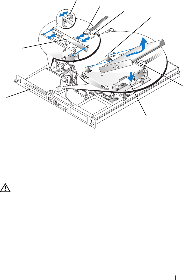
Figure 3-6. Removing and Installing the Optional Optical Drive
Installing the Optical Drive
CAUTION: Only trained service technicians are authorized to remove the system
cover and access any of the components inside the system. Before performing any
procedure, see your Product Information Guide for complete information about
safety precautions, working inside the computer and protecting against
electrostatic discharge.
1
Align the optical drive's mounting holes with the retaining pins on the
hard drive 0 bracket. See Figure 3-6.
2
Rotate the drive downward until it snaps into place.
1 interposer board 2 captive fasteners (2) 3 interface cable
4 power cable 5 retaining pins (4) 6 mounting holes (4)
7 bracket release lever 8 hard drive 0
5
7
2
8
1
3
6
4
book.book Page 61 Thursday, August 30, 2007 3:30 PM