
User's Manual


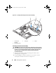
Table Of Contents
- Contents
- About Your System
- Using the System Setup Program
- Installing System Components
- Recommended Tools
- Inside the System
- Opening and Closing the System
- Cooling Shroud
- System Battery
- Optical Drive
- Configuring the Boot Drive
- Hard Drives
- Installing a SAS Controller Card
- Fan Assembly
- Optional PCI Fan Assembly
- Power Supply
- Expansion Cards
- Riser Card
- System Memory
- Processor
- Control Panel Assembly (Service-Only Procedure)
- System Board (Service-Only Procedure)
- Troubleshooting Your System
- Safety First-For You and Your System
- Start-Up Routine
- Checking the Equipment
- Responding to a Systems Management Software Alert Message
- Troubleshooting a Wet System
- Troubleshooting a Damaged System
- Troubleshooting the System Battery
- Troubleshooting the Power Supply
- Troubleshooting System Cooling Problems
- Troubleshooting System Memory
- Troubleshooting an Optical Drive
- Troubleshooting a Hard Drive
- Troubleshooting Expansion Cards
- Troubleshooting the Microprocessor
- Running the System Diagnostics
- Jumpers and Connectors
- Getting Help
- Glossary
- Index

Installing System Components 81
System Memory
The four memory module sockets are located on the system board adjacent to
the power supply and can accommodate 512 MB to 8 GB of unbuffered ECC
PC-5300/6400 (DDR2 667 or DDR 800) memory. See
Figure 6-2
for the
location of the memory module sockets.
You can upgrade the system memory by installing combinations of 512-MB,
1-GB, and 2-GB unbuffered memory modules. If you receive an error message
stating that maximum memory has been exceeded, see "System Messages" on
page 19 for more information. You can purchase memory upgrade kits from
Dell.
NOTE: The memory modules must be PC-5300/6400 compliant.
Memory Module Installation Guidelines
The memory module sockets are arranged in banks (1 and 2) on two channels
(A and B).
The memory module banks are identified as follows:
Bank 1: DIMM1_A and DIMM1_B
Bank 2: DIMM2_A and DIMM2_B
The memory module banks must be installed in identical pairs in
configurations that have more than one memory module. For example, if
socket DIMM1_A contains a 512-MB memory module, then the second
memory module to be installed must be a 512-MB memory module in socket
DIMM1_B.
Table 3-1 shows examples of different memory configurations, based on the
following guidelines:
• The minimum memory configuration is 512 MB.
• If only one memory module is installed, it must be installed in the
DIMM1_A socket.
• A bank must contain identical memory modules.
• Install the memory modules in bank 1 (DIMM1_
x
) before installing
memory modules in bank 2 (DIMM2_
x
).
• Installing three memory modules is not supported.
book.book Page 81 Thursday, August 30, 2007 3:30 PM