
Service Manual


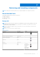

Table Of Contents
- OptiPlex 3000 Thin Client Service Manual
- Contents
- Working inside your computer
- Removing and installing components
- Recommended tools
- Screw list
- Major components of OptiPlex 3000 Thin Client
- Side cover
- Speaker
- Solid-state drive assembly
- Memory
- WLAN card
- Optional modules
- Removing the optional Type-C module
- Installing the optional Type-C module
- Removing the optional HDMI module
- Installing the optional HDMI module
- Removing the optional Serial module
- Installing the optional Serial module
- Removing the optional PS/2 keyboard/mouse module
- Installing the optional PS/2 keyboard/mouse module
- Coin-cell battery
- Heat sink
- Antenna Assembly
- SMA Antenna Assembly
- System board
- Drivers and downloads
- BIOS setup
- Troubleshooting
- Getting help and contacting Dell

Removing and installing components
NOTE: The images in this document may differ from your computer depending on the configuration you ordered.
Recommended tools
The procedures in this document may require the following tools:
● Phillips screwdriver #0
● Phillips screwdriver #1
● Torx #5 (T5) screwdriver
● Plastic scribe
Screw list
NOTE: When removing screws from a component, it is recommended to note the screw type, the quantity of screws, and
then place them in a screw storage box. This is to ensure that the correct number of screws and correct screw type is
restored when the component is replaced.
NOTE: Some computers have magnetic surfaces. Ensure that the screws are not left attached to such surfaces when
replacing a component.
NOTE: Screw color may vary with the configuration ordered.
Table 1. Screw list
Component Screw type Quantity Image
Side cover Thumb screw (#6-32) 1
M.2 2230 solid-state drive heat sink Captive screw 2 NA
M.2 2230 solid-state drive M2x3.5 1
WLAN card M2x3.5 1
Heat sink Captive screw 4 NA
System board M3x4
M3x5
2 (1 for M.2
WiFi standoff and
1 for M.2 SSD
standoff)
6 (5 for system
board and 1 for
speaker holder)
2
Removing and installing components 9