Precision 3470 Service Manual Regulatory Model: P137G Regulatory Type: P137G007/P137G008 April 2022 Rev.
Notes, cautions, and warnings NOTE: A NOTE indicates important information that helps you make better use of your product. CAUTION: A CAUTION indicates either potential damage to hardware or loss of data and tells you how to avoid the problem. WARNING: A WARNING indicates a potential for property damage, personal injury, or death. © 2022 Dell Inc. or its subsidiaries. All rights reserved. Dell Technologies, Dell, and other trademarks are trademarks of Dell Inc. or its subsidiaries.
Contents Chapter 1: Working inside your computer...................................................................................... 6 Safety instructions.............................................................................................................................................................. 6 Before working inside your computer....................................................................................................................... 6 Safety precautions....................
Heat sink.............................................................................................................................................................................. 37 Removing the heat sink and fan assembly - UMA...............................................................................................37 Installing the heat sink and fan assembly - UMA.................................................................................................38 Speakers...........................
Dummy SIM-card slot filler............................................................................................................................................. 90 Removing the dummy SIM-card slot filler.............................................................................................................90 Installing the dummy SIM-card slot filler............................................................................................................... 92 Palm-rest assembly................
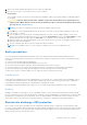
1 Working inside your computer Safety instructions Use the following safety guidelines to protect your computer from potential damage and to ensure your personal safety. Unless otherwise noted, each procedure included in this document assumes that you have read the safety information that shipped with your computer. WARNING: Before working inside your computer, read the safety information that is shipped with your computer. For more safety best practices, see the Regulatory Compliance home page at www.dell.
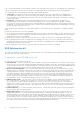
5. Remove any media card and optical disk from your computer, if applicable. 6. Enter the service mode, if you are able to power on your computer. Service Mode Service Mode is used to cut-off power, without disconnecting battery cable from system board prior conducting repairs in the computer. CAUTION: If you are unable to turn on the computer to put it into Service Mode or the computer does not support Service Mode then proceed to disconnect the battery cable.
Due to the increased density of semiconductors used in recent Dell products, the sensitivity to static damage is now higher than in previous Dell products. For this reason, some previously approved methods of handling parts are no longer applicable. Two recognized types of ESD damage are catastrophic and intermittent failures. ● Catastrophic – Catastrophic failures represent approximately 20 percent of ESD-related failures. The damage causes an immediate and complete loss of device functionality.
● ESD Packaging – All ESD-sensitive devices must be shipped and received in static-safe packaging. Metal, static-shielded bags are preferred. However, you should always return the damaged part using the same ESD bag and packaging that the new part arrived in. The ESD bag should be folded over and taped shut and all the same foam packing material should be used in the original box that the new part arrived in.
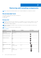
2 Removing and installing components NOTE: The images in this document may differ from your computer depending on the configuration you ordered. Recommended tools The procedures in this document may require the following tools: ● Phillips screwdriver #0 ● Plastic scribe Screw list NOTE: When removing screws from a component, it is recommended to note the screw type, the quantity of screws, and then place them in a screw storage box.
Table 1. Screw list (continued) Component Screw type Quantity eDP cable/bracket M2x3 2 USB Type-C support bracket M2x5 3 System board M2x3 4 Power button M2x2.5 2 Smart card reader M2x2.5 3 LED board M2x3 1 Keyboard assembly M2x2 18 Keyboard bracket M2x2 5 Display assembly M2.5x5 (display hinges to palm-rest assembly) 4 Display hinge M2.5x3 (display hinges to display back cover) 4 Display panel M2.
1. 3. 5. 7. 12 Base cover Speakers Assembly inner frame Keyboard assembly Removing and installing components 2. 4. 6. 8.
9. 11. 13. 15. Display assembly Coin-cell battery Heat sink and fan assembly WWAN card 10. 12. 14. 16. Battery LED board Power button/fingerprint board Solid-state drive WLAN card NOTE: Dell provides a list of components and their part numbers for the original system configuration purchased. These parts are available according to warranty coverages purchased by the customer. Contact your Dell sales representative for purchase options.
Installing the microSD card Prerequisites If you are replacing a component, remove the existing component before performing the installation procedure. About this task The following images indicate the location of the microSD card and provides a visual representation of the installation procedure. Steps 1. Align the microSD card to its slot on the computer. 2. Slide the microSD card into the slot until it clicks into place. Next steps 1. Follow the procedure in After working inside your computer.
Removing and installing components 15
Steps 1. Loosen the eight captive screws that secure the base cover to the palm-rest and keyboard assembly. 2. Using the flat-end of plastic scribe, pry the base cover from the U-shaped indents at the top edge of the base cover and continue to work on the sides to release the base cover from the palm-rest and keyboard assembly. 3. Lift the base cover off the palm-rest and keyboard assembly.
Steps 1. Align the screw holes on the base cover with the screw holes on the palm-rest assembly and keyboard assembly, and then snap the base cover into place. 2. Tighten the eight captive screws that secure the base cover to the palm-rest and keyboard assembly. Next steps 1. Install the microSD card. 2. Follow the procedure in After working inside your computer. Wireless card Removing the wireless card Prerequisites 1. Follow the procedure in Before working inside your computer. 2.
Removing and installing components
Steps 1. NOTE: When removing the wireless card from the computer, if the adhesive pad which helps secure the wireless card in place is removed from the computer along with the WLAN card, adhere it back to the computer. Loosen the single (M2x3.5) screw that secures the wireless-card bracket to the wireless card and system board. 2. Remove the wireless-card bracket from the wireless card. 3. Disconnect the antenna cables from the wireless card. 4.
Steps 1. Connect the antenna cables to the wireless card. The following table provides the antenna-cable color scheme: Table 2. Antenna-cable color scheme Connectors on the wireless card Antenna-cable color Silkscreen marking Main White MAIN △ (white triangle) Auxiliary Black AUX ▲ (black triangle) 2. Align the notch on the wireless card with the tab on the wireless-card slot on the system board. 3. Slide and insert the wireless card at an angle into the wireless-card slot on the system board.
Solid-state drives Removing the 2230 solid-state drive Prerequisites 1. Follow the procedure in Before working inside your computer. NOTE: Solid-state drives are fragile. Exercise care when handling the solid-state drive. NOTE: To avoid data loss, do not remove the solid-state drive while the computer is in sleep or on state. 2. Remove the microSD card. 3. Remove the base cover.
Steps 1. Remove the two (M2x3) screws that secures the thermal plate to the palm-rest assembly. 2. Remove the single (M2x3) screw securing the solid-state drive assembly in place. 3. Slide and remove the solid-state drive assembly from the computer. 4. Remove the single (M2x3) screw securing the solid-state drive bracket in place. 5. Slide and remove the solid-state drive bracket out of the computer. 6. Slide and remove the solid-state drive from the M.2 slot.
Steps 1. Align the notch on the M.2 2230 solid-state drive with the tab on the solid-state drive slot. 2. Slide the M.2 2230 solid-state drive into the solid-state drive slot on the system board 3. Replace the single screw (M2x3) that secures the solid-state drive to the holder and system board. NOTE: If the computer is not shipped with a M.2 2230 solid-state drive, you must obtain a customer kit that includes holder and a screw to install the M.2 2230 solid-state drive. 4.
NOTE: To avoid data loss, do not remove the solid-state drive while the computer is in sleep or on state. 2. Remove the microSD card. 3. Remove the base cover. About this task NOTE: Depending on the configuration ordered, your computer may support a 2280 solid-state drive, or a 2230 solid-state drive in M.2 slot. NOTE: This procedure applies only to computers shipped with a 2280 solid-state drive installed in M.2 slot.
The following images indicate the location of the 2280 solid-state drive that is installed in M.2 slot and provides a visual representation of the installation procedure. Steps 1. Align the notch on the M.2 2280 solid-state drive with the tab on the M.2 solid-state drive slot. 2. Slide the M.2 2280 solid-state drive into the M.2 solid-state drive slot on the system board. 3. Place the solid-state drive thermal plate over the solid-state drive. 4.
Steps 1. Using your fingertips, spread apart the securing clips on the memory-module slot until the memory module pops up. 2. Slide and remove the memory module from the memory-module slot. NOTE: Repeat step 1 to step 2 to remove any other memory modules installed in your computer. Installing the memory module Prerequisites If you are replacing a component, remove the existing component before performing the installation procedure. About this task NOTE: The system supports two memory slots.
Steps 1. Align the notch on the memory module with the tab on the memory-module slot. 2. . Slide the memory module firmly into the slot at an angle and press the memory module down until it clicks into place. NOTE: If you do not hear the click, remove the memory module and reinstall it. NOTE: Repeat step 1 to step 4 to install any other memory modules in your computer. Next steps 1. Install the microSD card. 2. Install the base cover. 3. Follow the procedure in After working inside your computer.
● Ensure any screws during the servicing of this product are not lost or misplaced, to prevent accidental puncture or damage to the battery and other system components. ● If the battery gets stuck inside your computer as a result of swelling, do not try to release it as puncturing, bending, or crushing a lithium-ion battery can be dangerous. In such an instance, contact Dell technical support for assistance. See www.dell.com/contactdell. ● Always purchase genuine batteries from www.dell.
About this task The following images indicate the location of the 4-cell (64 Wh) battery and provide a visual representation of the installation procedure. Steps 1. Align the screw holes on the 4-cell battery with the screw holes on the palm-rest and keyboard assembly. 2. Replace the two screws (M2x3) that secure the 4-cell battery to the palm-rest and keyboard assembly. 3. Connect the battery cable to the connector on the system board. Next steps 1. Install the microSD card. 2. Install the base cover. 3.
Steps 1. Flip the battery and unroute the battery cable from the routing guides on the battery. 2. Disconnect the battery cable from the connector on the battery. 3. Lift the battery cable away from the battery. Installing the 4-cell battery cable Prerequisites If you are replacing a component, remove the existing component before performing the installation procedure.
Steps 1. Connect the battery cable to the connector on the battery. 2. Route the battery cable through the routing guides on the battery. Next steps 1. 2. 3. 4. Install the battery. Install the microSD card. Install the base cover. Follow the procedure in After working inside your computer. Assembly inner frame Removing the assembly inner frame Prerequisites 1. 2. 3. 4. 5. Follow the procedure in Before working inside your computer. Remove the microSD card. Remove the base cover. Remove the battery.
Steps 1. Unroute the antenna cables from the routing guides on the assembly inner frame. 2. Remove the two screws (M2x5) and seven screws (M2x3) that secure the assembly inner frame to the system board and the palm-rest assembly. 3. Lift the assembly inner frame off the system board and the palm-rest assembly.
Installing the assembly inner frame Prerequisites If you are replacing a component, remove the existing component before performing the installation procedure. About this task The following image indicates the location of the assembly inner frame and provides a visual representation of the installation procedure.
Steps 1. Align the screw holes on the assembly inner frame with the screw holes on the system board and the palm-rest assembly. NOTE: Ensure that the tab on the top-left corner of the assembly inner frame is installed underneath the tab on the palm-rest assembly. Inner Frame palm-rest assembly 2. Replace the two screws (M2x5) and seven screws (M2x3) that secure the assembly inner frame to the system board and the palm-rest assembly. 3. Align and place the fingerprint bracket on the assembly inner frame.
Next steps 1. 2. 3. 4. 5. Install the battery. Install the wireless card. Install the base cover. Install the microSD card. Follow the procedure in After working inside your computer. LED board Removing the LED board Prerequisites 1. 2. 3. 4. 5. 6. 7. Follow the procedure in Before working inside your computer. Remove the microSD card. Remove the base cover. Remove the 2280 solid-state drive or 2230 solid-state drive. Remove the battery. Remove the wireless card. Remove the assembly inner frame.
Installing the LED board Prerequisites If you are replacing a component, remove the existing component before performing the installation procedure. About this task The following images indicate the location of the LED board and provide a visual representation of the installation procedure. Steps 1. Align the screw hole on the LED board with the screw hole on the palm-rest assembly. 2. Replace the single screw (M2x3) to secure the LED board to the palm-rest assembly. 3.
Heat sink Removing the heat sink and fan assembly - UMA Prerequisites 1. Follow the procedure in Before working inside your computer. 2. Remove the microSD card. 3. Remove the base cover. About this task The following images indicate the location of the heat sink and fan assembly and provide a visual representation of the removal procedure. Steps 1. Disconnect the system fan cable from the connector on the system board. 2. Remove the two screws (M2x5) that secure the system fan to the system board. 3.
Installing the heat sink and fan assembly - UMA Prerequisites If you are replacing a component, remove the existing component before performing the installation procedure. CAUTION: Incorrect alignment of the heat sink can damage the system board and processor. NOTE: If either the system board or the heat sink is replaced, use the thermal pad/paste provided in the kit to ensure that thermal conductivity is achieved.
Steps 1. Align the screw holes on the heat sink and fan assembly with the screw holes on the system board. 2. In sequential order (as indicated on the heat sink), tighten the four screws (M2x3) that secure the heat sink and fan assembly to the system board. 3. Replace the two screws (M2x5) that secure the system fan to the frame. 4. Connect the system fan cable to the connector on the system board. Next steps 1. Install the base cover. 2. Install the microSD card. 3.
Steps 1. Disconnect the speaker cable from the connector on the system board. 2. Peel the tape that secures the speaker cable to the palm-rest and keyboard assembly. 3. Note the speaker cable routing, and unroute the speaker cable from the routing guides on the palm-rest and keyboard assembly. 4. Lift the speakers, along with the cable, off the palm-rest and keyboard assembly.
Steps 1. Using the alignment posts and rubber grommets, place the speakers on the slots of the palm-rest and keyboard assembly. NOTE: Replace the cushion rubbers if any one of the cushion rubber is separated from the speakers. 2. Route the speaker cable through the bottom-left corner of the system and ensure that the speaker cables are routed firmly into the routing guides on the palm-rest and keyboard assembly. 3. Connect the speaker cable to the connector on the system board.
Next steps 1. 2. 3. 4. 5. Install the assembly inner frame. Install the battery. Install the base cover. Install the microSD card. Follow the procedure in After working inside your computer. System board Removing the system board Prerequisites 1. 2. 3. 4. 5. 6. 7. 8. Follow the procedure in Before working inside your computer. Remove the microSD card. Remove the base cover. Remove the 2280 solid-state drive or 2230 solid-state drive. Remove the battery. Remove the wireless card.
1. 2. 3. 4. 5. 6. 7. 8. 9. 10. 11. 12. 13. 14. 15.
Removing and installing components
Steps NOTE: For the models shipped with a fingerprint reader, disconnect the fingerprint reader cable from the connector on the system board before removing the system board from the palm-rest assembly and keyboard assembly. NOTE: When removing the system board to replace/access other parts, the system board can be removed and installed with the thermal assembly attached to simplify the procedure and preserve the thermal bond between the system board and heat-sink.
1. Remove the two (M2x3) screws that secure the eDP/display cable bracket to the system board. 2. Lift the eDP/display cable bracket away from the system. 3. Peel the tape that secures the display cable to the system board. 4. Using the pull tab, disconnect the display cable from the connector on the system board. 5. Disconnect IR camera cable from the connector on the system board (for models shipped with an IR camera). 6.
Removing and installing components 47
Steps NOTE: The system board can be removed and installed with the thermal module attached in order to simplify the procedure and preserve the thermal bond between the system board and heat-sink. In order to do so, technicians must also remove the two (M2x5) screws the secure the system fan to the system board. 1.
6. Connect the touchpad cable to the system board and close the latch to secure the cable to the system board. 7. Connect the USH board cable to the system board and close the latch to secure the cable to the system board. 8. Connect the touch screen cable from the connector on the system board (for models shipped with a touch screen). 9. Connect IR camera cable from the connector on the system board (for models shipped with an IR camera). 10.
Steps 1. Remove the two screws (M2x2.5) that secure the power-button board to the palm-rest assembly. NOTE: The removal of two screws applies to both models with and without the fingerprint reader. 2. Lift the power-button board off the palm-rest assembly. For models shipped with a fingerprint reader, make sure to disconnect the fingerprint reader FPC from the system board before removing the system board.
Installing the power button About this task The following image indicates the location of the power-button board and provide a visual representation of the installation procedure. Steps 1. Align and place the power-button board on the palm-rest assembly. 2. Replace the two (M2x2.5) screws that secure the power-button board to the palm-rest assembly. NOTE: This step applies to both models with and without the fingerprint reader. Next steps 1. 2. 3. 4. 5. 6. 7. 8. 9. 10. Install the system board.
Smart card reader Removing the smart card reader Prerequisites 1. 2. 3. 4. 5. 6. 7. Follow the procedure in Before working inside your computer. Remove the microSD card. Remove the base cover. Remove the 2280 solid-state drive or 2230 solid-state drive. Remove the battery. Remove the wireless card. Remove the assembly inner frame. About this task The following images indicate the location of the smart card reader and provide a visual representation of the removal procedure.
Steps 1. Open the latch and disconnect the smart card reader cable from the connector on the USH board. 2. Remove the three screws (M2x2.5) that secure the smart card reader to the palm-rest assembly. 3. Lift the smart card reader off the palm-rest assembly. Installing the smart card reader Prerequisites If you are replacing a component, remove the existing component before performing the installation procedure.
Next steps 1. 2. 3. 4. 5. 6. 7. Install the assembly inner frame. Install the battery. Install the wireless card. Install the 2280 solid-state drive or 2230 solid-state drive. Install the base cover. Install the microSD card. Follow the procedure in After working inside your computer. Coin-cell battery Removing the coin-cell battery Prerequisites 1. Follow the procedure in Before working inside your computer. CAUTION: Removing the coin-cell battery resets the BIOS setup program’s settings to default.
Installing the coin-cell battery Prerequisites If you are replacing a component, remove the existing component before performing the installation procedure. About this task The following image indicates the location of the coin-cell battery and provides a visual representation of the installation procedure. Steps Adhere the coin-cell battery to the slot on the palm-rest assembly. Next steps 1. 2. 3. 4. 5. 6. 7. Install the assembly inner frame. Install the battery. Install the wireless card.
4. 5. 6. 7. 8. 9. Remove the 2280 solid-state drive or 2230 solid-state drive. Remove the battery. Remove the wireless card. Remove the heat sink heat sink. Remove the assembly inner frame. Remove the system board. NOTE: The system board can be removed with the heat sink attached in order to simplify the procedure and preserve the thermal bond between the system board and heat sink.
3. Carefully lift the keyboard assembly from the palm-rest. 4. Remove the keyboard assembly off the palm-rest assembly. Installing the keyboard assembly Prerequisites If you are replacing a component, remove the existing component before performing the installation procedure. About this task NOTE: The system board can be installed with the heat sink attached in order to simplify the procedure and preserve the thermal bond between the system board and heat sink.
3. Connect the keyboard cable and keyboard backlit cable to its connectors on the touchpad. NOTE: For models shipped with a USH module, connect the USH cable to the keyboard bracket. Next steps 1. 2. 3. 4. 5. 6. 7. 8. 9. Install the system board. Install the heat sink. Install the assembly inner frame. Install the battery. Install the wireless card. Install the 2280 solid-state drive or 2230 solid-state drive. Install the base cover. Install the microSD card.
Steps 1. Remove the five (M2x2) screws that secure the keyboard to the keyboard bracket. 2. Remove the keyboard from the keyboard bracket.
Installing the keyboard bracket Prerequisites If you are replacing a component, remove the existing component before performing the installation procedure. About this task NOTE: The system board can be installed with the heat sink attached in order to simplify the procedure and preserve the thermal bond between the system board and heat sink. The following image indicates the location of the keyboard bracket and provides a visual representation of the installation procedure.
Steps 1. Align and place the keyboard on the keyboard bracket. 2. Replace the five (M2x2) screws to secure the keyboard to the keyboard bracket. Next steps 1. 2. 3. 4. 5. 6. 7. 8. 9. 10. 11. Install the keyboard assembly. Install the system board. Install the heat sink. Install the assembly inner frame. Install the battery. Install the memory modules. Install the wireless card. Install the 2280 solid-state drive or 2230 solid-state drive. Install the base cover. Install the microSD card.
Removing and installing components
Steps 1. Remove the two (M2x3) screws that secure the eDP cable bracket to the system board. 2. Lift the eDP cable bracket away from the system. 3. Peel the tape that secures the display cable to the system board. 4. Using the pull tab, disconnect the display cable from the connector on the system board.
5. Disconnect the eDP cable from the connector on the system board and unroute it from the routing guide. 6. Disconnect the IR camera cable from its connector on the system board (for models shipped with an IR camera). 7. Disconnect the touchscreen cable from its connector on the system board (for models shipped with a touchscreen). 8. Peel the adhesive tape partially and unroute the WLAN antenna cables from the routing guides on the system board. 9. Remove the four (M2.
Removing and installing components 65
Steps 1. Place the display assembly on the system. Align the screw holes on the display hinges with screw holes on the palm-rest assembly. 2. Replace the four (M2.5x5) screws that secure the display hinges to the palm-rest assembly. 3. Close the display. 4. Route the WLAN antenna cables through the routing guide and adhere the tape to secure the cables to the system board. 5. Route the display and eDP cable through the routing guide on the system board. 6.
Next steps 1. 2. 3. 4. Install the wireless card. Install the base cover. Install the microSD card. Follow the procedure in After working inside your computer. Display bezel Removing the display bezel Prerequisites 1. 2. 3. 4. 5. Follow the procedure in Before working inside your computer. Remove the microSD card. Remove the base cover. Remove the wireless card. Remove the display assembly.
Steps NOTE: The display bezel is adhered to the display panel with adhesive. Insert a plastic scribe into the recesses near both hinge caps to start the prying process to release the display bezel. Pry along the outside edge of the display bezel and work your way around the entire display bezel until the display bezel is separated from the display cover. CAUTION: Carefully pry and remove the display bezel to minimize the risk of display panel damages. 1.
Steps 1. Align and place the display bezel on the display assembly. 2. Gently snap the display bezel into place. Next steps 1. 2. 3. 4. 5. Install the display assembly. Install the wireless card. Install the base cover. Install the microSD card. Follow the procedure in After working inside your computer. Display panel Removing the display panel Prerequisites 1. 2. 3. 4. 5. 6. Follow the procedure in Before working inside your computer. Remove the microSD card. Remove the base cover.
Removing and installing components
Removing and installing components 71
Removing and installing components
Steps NOTE: The display panel is preassembled with the display brackets as a single service part. Do not pull the Stretch Release (SR) tapes and separate the brackets from the display panel. 1. Remove the two screws (M2.5x3) that secure the display panel to the display back cover. NOTE: While removing the display panel, disengage the display panel tabs from the display cover before flipping it over. 2. Lift and open the display panel to access the display cable. 3.
Removing and installing components
Removing and installing components 75
Steps 1. Connect the display cable to the connector on the display panel and close the latch. 2. Adhere the clear tape to cover the display cable connector. 3. Adhere the conductive tape to secure the display cable to the display panel. 4. Close the display panel and the display back cover to assemble. NOTE: Ensure that the display panel tabs are inserted into the slots on the display cover. 5. Replace the two (M2.5x3) screws to secure the display panel to the display back cover. Next steps 1. 2. 3. 4. 5.
3. 4. 5. 6. 7. 8. Remove Remove Remove Remove Remove Remove the the the the the the base cover. wireless card. display assembly. display bezel. display panel. display hinges. About this task The following images indicate the location of the camera module and provide a visual representation of the removal procedure. Steps 1. Peel the tape that secures the camera cable. NOTE: An abrupt peeling may also remove the camera shutter from the display bezel and damage the camera shutter. 2.
4. Pry up the camera module ensuring that the two tiny pegs used to secure the camera module in place are not damaged throughout the prying process. Carefully lift the camera module from the display back cover. Installing the camera Prerequisites If you are replacing a component, remove the existing component before performing the installation procedure. About this task The following images indicate the location of the camera and provide a visual representation of the installation procedure.
Steps 1. Align and place the camera module into the slot on the display back cover. 2. Connect the camera cable to the connector on the camera module. 3. Adhere the tape to secure the camera cable in place. Next steps 1. 2. 3. 4. 5. 6. 7. 8. Install the display hinge. Install the display panel. Install the display bezel. Install the display assembly. Install the wireless card. Install the base cover. Install the microSD card. Follow the procedure in After working inside your computer.
Steps 1. Peel the tape that secures the infrared camera cable. NOTE: An abrupt peeling may also remove the camera shutter from the display bezel and damage the camera shutter. 2. Lift the latch and disconnect the infrared camera cable from the connector on the camera module. 3. Carefully pry up the camera module starting from the prying point indicated by an etched arrow at the bottom edge of the camera module. 4.
Installing the infrared camera Prerequisites If you are replacing a component, remove the existing component before performing the installation procedure. About this task The following image indicates the location of the infrared camera and provides a visual representation of the installation procedure. Steps 1. Align and place the infrared camera module into the slot on the display back cover. 2. Connect the infrared camera cable to the connector on the camera module.
3. Adhere the tape to secure the infrared camera cable in place. Next steps 1. 2. 3. 4. 5. 6. 7. Install the display panel. Install the display bezel. Install the display assembly. Install the wireless card. Install the base cover. Install the microSD card. Follow the procedure in After working inside your computer. eDP/display cable Removing the eDP/display cable Prerequisites 1. 2. 3. 4. 5. 6. 7. Follow the procedure in Before working inside your computer. Remove the microSD card.
Steps 1. Disconnect the eDP/display cable from the connector on the camera module. 2. Peel the conductive tape and unroute the eDP/display cable to release it from adhesive and lift the eDP/display cable from the display back cover. Installing the eDP cable Prerequisites If you are replacing a component, remove the existing component before performing the installation procedure.
Steps 1. Connect the eDP/display cable to the connector on the camera. 2. Adhere the eDP/display cable to the display back cover. 3. Adhere the conductive tape and route the eDP/display cable to the display back cover. Next steps 1. 2. 3. 4. 5. 6. 7. Install the display panel. Install the display bezel. Install the display assembly. Install the wireless card. Install the base cover. Install the microSD card. Follow the procedure in After working inside your computer.
3. 4. 5. 6. 7. Remove Remove Remove Remove Remove the the the the the base cover. wireless card. display assembly. display bezel. display panel. About this task NOTE: This procedure applies only to computers shipped with a sensor board. The following image indicates the location of the sensor board and provide a visual representation of the removal procedure. Steps 1. Open the latch and disconnect the LED cable from connector on the sensor board. 2.
Steps 1. Align and place the sensor board on the display back cover. 2. Connect the LED cable to the connector on the sensor board and close the latch. Next steps 1. 2. 3. 4. 5. 6. 7. Install the display panel. Install the display bezel. Install the display assembly. Install the wireless card. Install the base cover. Install the microSD card. Follow the procedure in After working inside your computer. Display hinges Removing the display hinges Prerequisites 1. 2. 3. 4. 5. 6. 7.
Steps 1. Remove the two (M2.5x3) screws that secure the right hinge to the display back cover. 2. Lift and remove the right hinge from the display back cover. 3. Remove the two (M2.5x3) screws that secure the left hinge to the display back cover. 4. Lift and remove the left hinge from the display back cover. Installing the display hinges Prerequisites If you are replacing a component, remove the existing component before performing the installation procedure.
Steps 1. Align the screw hole on the left hinge with the screw hole on the display back cover. 2. Replace the two (M2.5x3) screws to secure the left hinge to the display back cover. 3. Align the screw hole on the right hinge with the screw hole on the display back cover. 4. Replace the two (M2.5x3) screws to secure the right hinge to the display back cover. Next steps 1. 2. 3. 4. 5. 6. 7. 88 Install the display panel. Install the display bezel. Install the display assembly. Install the wireless card.
Display back cover Removing the display back cover Prerequisites 1. 2. 3. 4. 5. 6. 7. 8. 9. 10. 11. Follow the procedure in Before working inside your computer. Remove the microSD card. Remove the base cover. Remove the wireless card. Remove the display assembly. Remove the display bezel. Remove the display panel. Remove the camera module. Remove the eDP/display cable. Remove the sensor board. Remove the display hinges.
About this task The following image indicates the location of the display back cover and provides a visual representation of the installation procedure. Steps Place the display back cover on a flat surface. Next steps 1. 2. 3. 4. 5. 6. 7. 8. 9. 10. 11. Install the display hinge. Install the sensor board. Install the eDP/display cable. Install the camera module. Install the display panel. Install the display bezel. Install the display assembly. Install the wireless card. Install the base cover.
7. 8. 9. 10. 11. 12. 13. 14. 15. 16. Remove the wireless card. Remove the heat sink heat sink. Remove the assembly inner frame. Remove the system board. NOTE: The system board can be removed with the heat sink attached in order to simplify the procedure and preserve the thermal bond between the system board and heat sink. Remove the power-button board. Remove the LED board. Remove the smart card reader. Remove the Keyboard assembly. Remove the display assembly. Remove the palm-rest assembly.
2. Lift the dummy SIM-card slot filler out of the palm-rest assembly. Installing the dummy SIM-card slot filler Prerequisites If you are replacing a component, remove the necessary component before the installation procedure.
About this task The following images indicate the location of the dummy SIM-card slot filler and provides a visual representation of the dummy SIM-card slot filler installation procedure. Steps 1. Place the dummy SIM-card slot filler into its compartment on the palm rest. NOTE: Ensure that the dummy SIM-card slot filler is aligned with the ribs on the palm-rest assembly.
2. Press the dummy SIM-card slot filler until it clicks into place and ensure it fits securely into the SIM card slot.
Next steps 1. 2. 3. 4. 5. 6. 7. 8. 9. 10. 11. 12. 13. 14. 15. 16. Install the palm-rest assembly Install the display assembly. Install the keyboard assembly. Install the smart card reader. Install the LED board. Install the power-button board. Install the system board. Install the heat sink. Install the assembly inner frame. Install the battery. Install the memory modules. Install the wireless card. Install the 2280 solid-state drive or 2230 solid-state drive. Install the base cover.
8. Remove the heat sink heat sink. 9. Remove the assembly inner frame. 10. Remove the system board. NOTE: The system board can be removed with the heat sink attached in order to simplify the procedure and preserve the thermal bond between the system board and heat sink. 11. Remove the power-button board. 12. Remove the LED board. 13. Remove the smart card reader. 14. Remove the Keyboard assembly. 15. Remove the display assembly. 16. Remove the dummy SIM-card slot filler.
Steps Place the palm-rest assembly on a flat surface. NOTE: For models shipped with WLAN antennas only, the filler must be removed then re-installed when replacing the palm-rest assembly.
Next steps 1. 2. 3. 4. 5. 6. 7. 8. 9. 10. 11. 12. 13. 14. 15. 16. 98 Install the dummy SIM-card slot filler. Install the display assembly. Install the keyboard assembly. Install the smart card reader. Install the LED board. Install the power-button board. Install the system board. Install the heat sink. Install the assembly inner frame. Install the battery. Install the memory modules. Install the wireless card. Install the 2280 solid-state drive or 2230 solid-state drive. Install the base cover.
3 Drivers and downloads When troubleshooting, downloading or installing drivers it is recommended that you read the Dell Knowledge Based article, Drivers and Downloads FAQ 000123347.
4 BIOS setup CAUTION: Unless you are an expert computer user, do not change the settings in the BIOS Setup program. Certain changes can make your computer work incorrectly. NOTE: Depending on the computer and its installed devices, the items listed in this section may or may not be displayed. NOTE: Before you change BIOS Setup program, it is recommended that you write down the BIOS Setup program screen information for future reference.
The one-time boot menu displays the devices that you can boot from including the diagnostic option. The boot menu options are: ● Removable Drive (if available) ● M.2 Drive (if available) NOTE: XXX denotes the M.2 drive number. ● Optical Drive (if available) ● NVMe Drives ● Diagnostics The boot sequence screen also displays the option to access the System Setup screen. System setup options NOTE: Depending on your computer and its installed devices, the items listed in this section may or may not appear.
Table 4. System setup options—System information menu (continued) Overview 64-Bit Technology Displays whether 64-bit technology is used. Memory Information Memory Installed Displays the total computer memory installed. Memory Available Displays the total computer memory available. Memory Speed Displays the memory speed. Memory Channel Mode Displays single or dual channel mode. Memory Technology Displays the technology used for the memory. DIMM_SLOT 1 Displays the DIMM 1 memory size.
Table 6. System setup options—Integrated Devices menu Integrated Devices Date/Time Displays the current date in MM/DD/YYYY format and current time in HH:MM:SS AM/PM format. Camera Enables or disable the camera. By default, the Enable Camera option is selected Audio Enable Audio Enable or disable the integrated audio controller. By default, all the options are enabled. USB/Thunderbolt Configuration ● Enable or disable booting from USB mass storage devices connected to external USB ports.
Table 6. System setup options—Integrated Devices menu (continued) Integrated Devices By default, the Enable Unobtrusive Mode option is disabled. Table 7. System setup options—Storage menu Storage SMART Reporting Enable SMART Reporting Enable or disable Self-Monitoring, Analysis, and Reporting Technology (SMART) during computer startup. By default, the Enable SMART Reporting option is not enabled. Drive Information M.2 PCIe SSD-1 Type Displays the M.2 PCIe SSD-1 type information of the computer.
Table 9. System setup options—Connection menu (continued) Connection By default, the Bus Mode PCIe option is enabled. WLAN Enable or disable the internal WLAN device By default, the option enabled. Bluetooth Enable or disable the internal Bluetooth device By default, the option enabled. Contactless smartcard/NFC Enable or disable the internal Contactless smartcard/NFC device By default, the option enabled.
Table 10. System setup options—Power menu (continued) Power Thermal Management Enables to cool the fan and processor heat management to adjust the computer performance, noise, and temperature. By default, the Optimized option is enabled. USB Wake Support Wake on Dell USB-C Dock When enabled, connecting a Dell USB-C Dock will wake the computer from standby. By default, the Wake on Dell USB-C Dock option is enabled. Block Sleep Enables to block entering sleep (S3) mode in the operating system.
Table 11. System setup options—Security menu (continued) Security Data Wipe on Next Boot Start Data Wipe Enable or disable the data wipe on next boot. By default, the option is enabled. Absolute Enable or disable or permanently disable the BIOS module interface of the optional Absolute Persistence Module service from Absolute software. By default, the option is enabled.
Table 12. System setup options—Passwords menu (continued) Passwords Enable Allow Non-Admin PSID Revert Controls access to the Physical Security ID (PSID) revert of NVMe hard-drives from the Dell Security Manager prompt. By default, the option is disabled. Table 13. System setup options—Update, Recovery menu Update, Recovery UEFI Capsule Firmware Updates Enable or disable BIOS updates through UEFI capsule update packages. By default, the option is enabled.
Table 14. System setup options—System Management menu (continued) System Management MEBx Hotkey Allows the user to use Ctrl+P hotkey to access MEBx USB Provision When enabled, Intel AMT can be provisioned using the local provisioning file through a USB storage device Table 15. System setup options—Keyboard menu Keyboard Numlock Enable Enable or disable the Numlock function when the computer boots. By default, the option is enabled. Fn Lock Options By default, the Fn lock option is enabled.
Table 17. System setup options—Performance menu (continued) Performance Intel SpeedStep Enable Intel SpeedStep Technology Enables the computer to dynamically adjust processor voltage and core frequency, decreasing average power consumption and heat production. By default, the option is enabled. C-States Control Enable C-State Control Enable or disable additional processor sleep states. By default, the option is enabled.
unnecessary operating system re-install. For more information on this subject, search in the Knowledge Base Resource at www.dell.com/support. Steps 1. Go to www.dell.com/support. 2. Click Product support. In the Search support box, enter the Service Tag of your computer, and then click Search. NOTE: If you do not have the Service Tag, use the SupportAssist feature to automatically identify your computer. You can also use the product ID or manually browse for your computer model. 3.
system will ask for this on each reboot. If the recovery key is not known this can result in data loss or an unnecessary operating system re-install. For more information on this subject, search in the Knowledge Base Resource at www.dell.com/support. BIOS Update You can run the BIOS update file from Windows using a bootable USB drive or you can also update the BIOS from the F12 One-Time boot menu on the computer.
Assigning a system setup password Prerequisites You can assign a new System or Admin Password only when the status is in Not Set. About this task To enter the system setup, press F12 immediately after a power-on or reboot. Steps 1. In the System BIOS or System Setup screen, select Security and press Enter. The Security screen is displayed. 2. Select System/Admin Password and create a password in the Enter the new password field.
Steps 1. Remove the base cover. 2. Disconnect the battery cable from the system board. 3. Remove the coin-cell battery. 4. Wait for one minute. 5. Replace the coin-cell battery. 6. Connect the battery cable to the system board. 7. Replace the base cover. Clearing BIOS (System Setup) and System passwords About this task To clear the system or BIOS passwords, contact Dell technical support as described at www.dell.com/contactdell.
5 Troubleshooting Handling swollen Lithium-ion batteries Like most laptops, Dell laptops use lithium-ion batteries. One type of lithium-ion battery is the lithium-ion polymer battery. Lithium-ion polymer batteries have increased in popularity in recent years and have become standard in the electronics industry due to customer preferences for a slim form factor (especially with newer ultra-thin laptops) and long battery life.
● Run thorough tests to introduce additional test options to provide extra information about the failed device(s) ● View status messages that inform you if tests are completed successfully ● View error messages that inform you of problems encountered during testing NOTE: Some tests for specific devices require user interaction. Always ensure that you are present at the computer terminal when the diagnostic tests are performed. For more information, see https://www.dell.com/support/kbdoc/000180971.
LCD Power rail test (L-BIST) L-BIST is an enhancement to the single LED error code diagnostics and is automatically initiated during POST. L-BIST will check the LCD power rail. If there is no power being supplied to the LCD (i.e., the L-BIST circuit fails), the battery status LED will flash either an error code [2,8] or an error code [2,7]. NOTE: If L-BIST fails, LCD-BIST cannot function as no power will be supplied to the LCD. How to invoke L-BIST Test: 1. Press the power button to start the system. 2.
Table 21. System-diagnostic lights (continued) Blinking pattern Amber White Problem description Suggested resolution 1 6 Generic catch-all for ungraceful EC code flow errors Disconnect all power source (AC, battery, coin cell) and drain flea power by pressing and holding down power button for 3~5 seconds.
Table 21. System-diagnostic lights (continued) Blinking pattern Amber White Problem description Suggested resolution ● ● ● 3 7 Timeout waiting on ME to reply to HECI message. RTC reset. If problem persists, replace the system board. Disconnect all power source (AC, battery, coin cell) and drain flea power by pressing and holding down power button 3~5 seconds to ensure all power are drained. Run "BIOS recovery from USB", and the instructions are in the website Dell support.
Backup media and recovery options It is recommended to create a recovery drive to troubleshoot and fix problems that may occur with Windows. Dell proposes multiple options for recovering Windows operating system on your Dell PC. For more information. see Dell Windows Backup Media and Recovery Options. WiFi power cycle About this task If your computer is unable to access the internet due to WiFi connectivity issues a WiFi power cycle procedure may be performed.
6 Getting help and contacting Dell Self-help resources You can get information and help on Dell products and services using these self-help resources: Table 22. Self-help resources Self-help resources Resource location Information about Dell products and services www.dell.com My Dell app Tips Contact Support In Windows search, type Contact Support, and press Enter. Online help for operating system www.dell.com/support/windows www.dell.