
User Manual
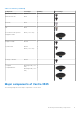
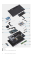
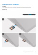
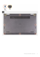
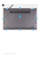
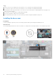
Table Of Contents
- Vostro 3525 Service Manual
- Contents
- Working inside your computer
- Removing and installing components
- Recommended tools
- Screw list
- Major components of Vostro 3525
- Secure Digital (SD) Card
- Base cover
- Battery
- Memory modules
- M.2 solid-state drive
- Wireless card
- Fan
- Speakers
- Hard drive assembly
- I/O board
- I/O daughter board FFC
- Heat sink
- Power-button board
- Power button with fingerprint reader
- Display assembly
- Display bezel
- Display panel
- Hinge caps
- Hinges
- Camera module
- eDP cable
- Display cover and antenna assembly
- Touchpad
- Power-adapter port
- System board
- Palm-rest and keyboard assembly
- Drivers and downloads
- BIOS setup
- Troubleshooting
- Handling swollen Lithium-ion batteries
- Dell SupportAssist Pre-boot System Performance Check diagnostics
- Built-in self-test (BIST)
- System-diagnostic lights
- Recovering the operating system
- Real-Time Clock (RTC Reset)
- Backup media and recovery options
- WiFi power cycle
- Drain residual flea power (perform hard reset)
- Getting help and contacting Dell

Table 1. Screw list (continued)
Component Screw type Quantity Screw image
Hard-drive assembly
Hard-drive bracket
M2x3.5
M3x3
4
4
Heat sink M2x3 4
Fan M2x5 2
Power button with optional
fingerprint reader
M2x2 (O.D. 5 mm) 1
Display assembly M2.5x5 4
System board M2x3.5
M2x2 (O.D. 5 mm)
4
1
USB type-C bracket M2x3.5 2
Touchpad
Touchpad bracket
M2x2 big head (O.D. 5
mm)
M2x2 big head (O.D. 5
mm)
2
3
Major components of Vostro 3525
The following image shows the major components of Vostro 3525.
Removing and installing components
11