
User Manual

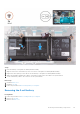
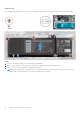
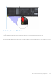
Table Of Contents
- Vostro 3525 Service Manual
- Contents
- Working inside your computer
- Removing and installing components
- Recommended tools
- Screw list
- Major components of Vostro 3525
- Secure Digital (SD) Card
- Base cover
- Battery
- Memory modules
- M.2 solid-state drive
- Wireless card
- Fan
- Speakers
- Hard drive assembly
- I/O board
- I/O daughter board FFC
- Heat sink
- Power-button board
- Power button with fingerprint reader
- Display assembly
- Display bezel
- Display panel
- Hinge caps
- Hinges
- Camera module
- eDP cable
- Display cover and antenna assembly
- Touchpad
- Power-adapter port
- System board
- Palm-rest and keyboard assembly
- Drivers and downloads
- BIOS setup
- Troubleshooting
- Handling swollen Lithium-ion batteries
- Dell SupportAssist Pre-boot System Performance Check diagnostics
- Built-in self-test (BIST)
- System-diagnostic lights
- Recovering the operating system
- Real-Time Clock (RTC Reset)
- Backup media and recovery options
- WiFi power cycle
- Drain residual flea power (perform hard reset)
- Getting help and contacting Dell

● Do not bend the battery.
● Do not use tools of any kind to pry on or against the battery.
● Ensure any screws during the servicing of this product are not lost or misplaced, to prevent accidental
puncture or damage to the battery and other system components.
● If the battery gets stuck inside your computer as a result of swelling, do not try to release it as puncturing,
bending, or crushing a lithium-ion battery can be dangerous. In such an instance, contact Dell technical
support for assistance. See www.dell.com/contactdell.
● Always purchase genuine batteries from www.dell.com or authorized Dell partners and resellers.
● Swollen batteries should not be used and should be replaced and disposed properly. For guidelines on how to
handle and replace swollen Lithium-ion batteries, see Handling swollen Lithium-ion batteries.
Removing the 3-cell battery
Prerequisites
1. Follow the procedure in Before working inside your computer.
2. Remove the SD card.
3. Remove the base cover.
About this task
The following image indicates the location of the 3-cell battery and provides a visual representation of the removal procedure.
Removing and installing components
23