
User Manual
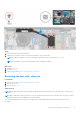
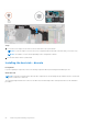
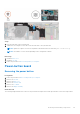
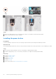
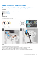
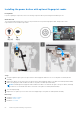
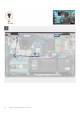
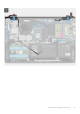
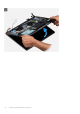
Table Of Contents
- Vostro 3525 Service Manual
- Contents
- Working inside your computer
- Removing and installing components
- Recommended tools
- Screw list
- Major components of Vostro 3525
- Secure Digital (SD) Card
- Base cover
- Battery
- Memory modules
- M.2 solid-state drive
- Wireless card
- Fan
- Speakers
- Hard drive assembly
- I/O board
- I/O daughter board FFC
- Heat sink
- Power-button board
- Power button with fingerprint reader
- Display assembly
- Display bezel
- Display panel
- Hinge caps
- Hinges
- Camera module
- eDP cable
- Display cover and antenna assembly
- Touchpad
- Power-adapter port
- System board
- Palm-rest and keyboard assembly
- Drivers and downloads
- BIOS setup
- Troubleshooting
- Handling swollen Lithium-ion batteries
- Dell SupportAssist Pre-boot System Performance Check diagnostics
- Built-in self-test (BIST)
- System-diagnostic lights
- Recovering the operating system
- Real-Time Clock (RTC Reset)
- Backup media and recovery options
- WiFi power cycle
- Drain residual flea power (perform hard reset)
- Getting help and contacting Dell

Steps
1. Place the heat sink on the system board.
2. Tighten the four captive screws that secure the heat sink to the system board.
NOTE: Tighten the captive screws in the sequential order mentioned on the heat sink [1 > 2 > 3 > 4].
NOTE: The number of screws varies depending on the configuration ordered.
Next steps
1. Install the base cover.
2. Install the SD card.
3. Follow the procedure in After working inside your computer.
Removing the heat sink - discrete
Prerequisites
1. Follow the procedure in Before working inside your computer.
2. Remove the SD card.
3. Remove the base cover.
About this task
NOTE:
The heat sink may become hot during normal operation. Allow sufficient time for the heat sink to cool before you
touch it.
NOTE: For maximum cooling of the processor, do not touch the heat transfer areas on the heat sink. The oils in your skin
can reduce the heat transfer capability of the thermal grease.
The following images indicate the location of the discrete heat sink and provide a visual representation of the removal
procedure.
Removing and installing components
51