
User Manual
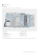
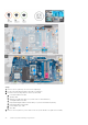

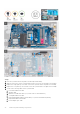
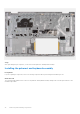
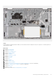
Table Of Contents
- Vostro 3525 Service Manual
- Contents
- Working inside your computer
- Removing and installing components
- Recommended tools
- Screw list
- Major components of Vostro 3525
- Secure Digital (SD) Card
- Base cover
- Battery
- Memory modules
- M.2 solid-state drive
- Wireless card
- Fan
- Speakers
- Hard drive assembly
- I/O board
- I/O daughter board FFC
- Heat sink
- Power-button board
- Power button with fingerprint reader
- Display assembly
- Display bezel
- Display panel
- Hinge caps
- Hinges
- Camera module
- eDP cable
- Display cover and antenna assembly
- Touchpad
- Power-adapter port
- System board
- Palm-rest and keyboard assembly
- Drivers and downloads
- BIOS setup
- Troubleshooting
- Handling swollen Lithium-ion batteries
- Dell SupportAssist Pre-boot System Performance Check diagnostics
- Built-in self-test (BIST)
- System-diagnostic lights
- Recovering the operating system
- Real-Time Clock (RTC Reset)
- Backup media and recovery options
- WiFi power cycle
- Drain residual flea power (perform hard reset)
- Getting help and contacting Dell

Steps
1. Remove the two (M2.5x5) screws from the right hinge.
2. Pry open the right-display hinge at an angle of 90 degrees.
3. Disconnect the following cables from the system board:
a. I/O board Flexible Flat cable
b. Speaker cable
c. Hard drive Flexible Flat cable (for systems with 2.5-inch hard drive)
d. Touchpad Flexible Flat cable
e. Keyboard backlight Flexible Printed cable (for systems with backlit keyboard)
f. Keyboard Flexible Printed cable
g. Power adapter port cable
h. eDP cable
4. Remove the four (M2x3.5) screws that secure the system board to the palm-rest assembly.
94
Removing and installing components